Lingual bracket

a lingual bracket and bracket technology, applied in the field of lingual orthodontic brackets, can solve the problems of not sufficiently developing the force required for the rotation of teeth, unable to propose satisfactory solutions for lingual applications, and unable to achieve satisfactory results. , to achieve the effect of enlarging the resistance against the arch wir

Inactive Publication Date: 2004-04-15
HEISER WOLFGANG +1
View PDF18 Cites 17 Cited by
  • Summary
  • Abstract
  • Description
  • Claims
  • Application Information

AI Technical Summary

Benefits of technology

0024] A special advantage of the invention, which results from the position of the slot opening created by the invention is furthermore, that safety lugs for the free end of the closing spring, where such closing spring is used instead of a ligature, do not have to be used, and in the case of brackets for the upper anterior teeth and possibly the upper canine teeth these safety lugs are also advantageously not necessary. These brackets are therefore extremely flat, which is important to prevent that when closing the jaws, the lower anterior teeth gripping behind the upper anterior teeth hit the brackets fixed to the upper anterior teeth.
0025] Such a safety lug is e.g. known from U.S. Pat. No. 4,492,573 and it is indispensable in the bracket shown there, since the opening and closing movements of the spring, which is U-shaped in this document and whose one leg covers the slot, extend transversely to the direction in which the arch wire would leave the slot. If the arch wire, for whatever reason, was urged out of the slot in the closing position of the spring, it would bend the spring excessively over its resiliency limit and would thereby destroy the entire bracket, if the free end of the spring leg covering the slot was not secured below a projecting lug. In the bracket according to the invention, an arch wire urged out of the slot in the opening direction of the closing spring acts on this spring and only pivots the spring without destroying it. The safety lug is therefore basically dispensable in this bracket. When it is still used, e.g. in the area of the canine teeth, it serves there on the one hand for enlarging the resistance against the arch wire being pressed out of the slot, and on the other hand the wire is released when a certain force is exceeded and thus, the tooth is automatically protected against overload. By this lug, the desired opening resistance of the spring can be produced.

Problems solved by technology

The disadvantage of this construction is that the pressure applied by the arch wire, which in the case of a lingual application of the bracket is frequently directed inwardly, i.e. in the direction of the oral cavity, must be received by the closing plate and by its spring holding the closing plate in the closing direction.
The support of the arch wire is therefore not rigid but somehow resilient, which does not sufficiently develop the forces required for the rotation of a tooth.
For securing the arch wire, ligatures in the form of highly-resilient O-rings (usually made of rubber) are provided for this bracket, so that this bracket reveals similar disadvantages in use and when replacing the arch wire as the above-mentioned bracket.
However, satisfactory solutions have not been proposed for lingual applications.
On small brackets, however, the lever arm available for the arch wire for applying directional forces, particularly for rotation and torque, is very small.
Resilient supports, such as by means of O-rings, as in the prior art, would significantly reduce the effect of the arch wire in this area and would often develop insufficient forces for correcting a rotation.
If the arch wire, for whatever reason, was urged out of the slot in the closing position of the spring, it would bend the spring excessively over its resiliency limit and would thereby destroy the entire bracket, if the free end of the spring leg covering the slot was not secured below a projecting lug.

Method used


Image

  • Lingual bracket
  • Lingual bracket
  • Lingual bracket

Examples


Embodiment Construction

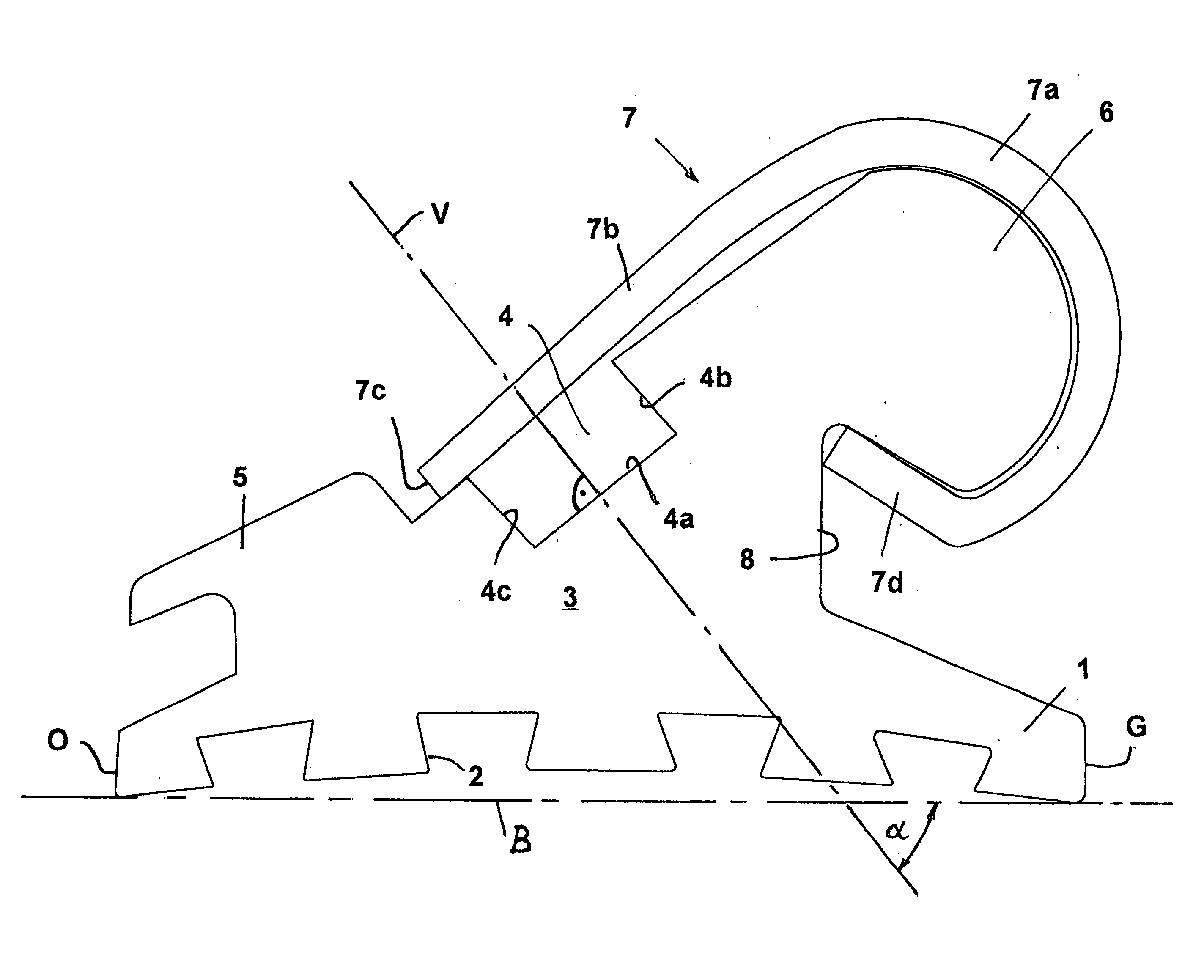
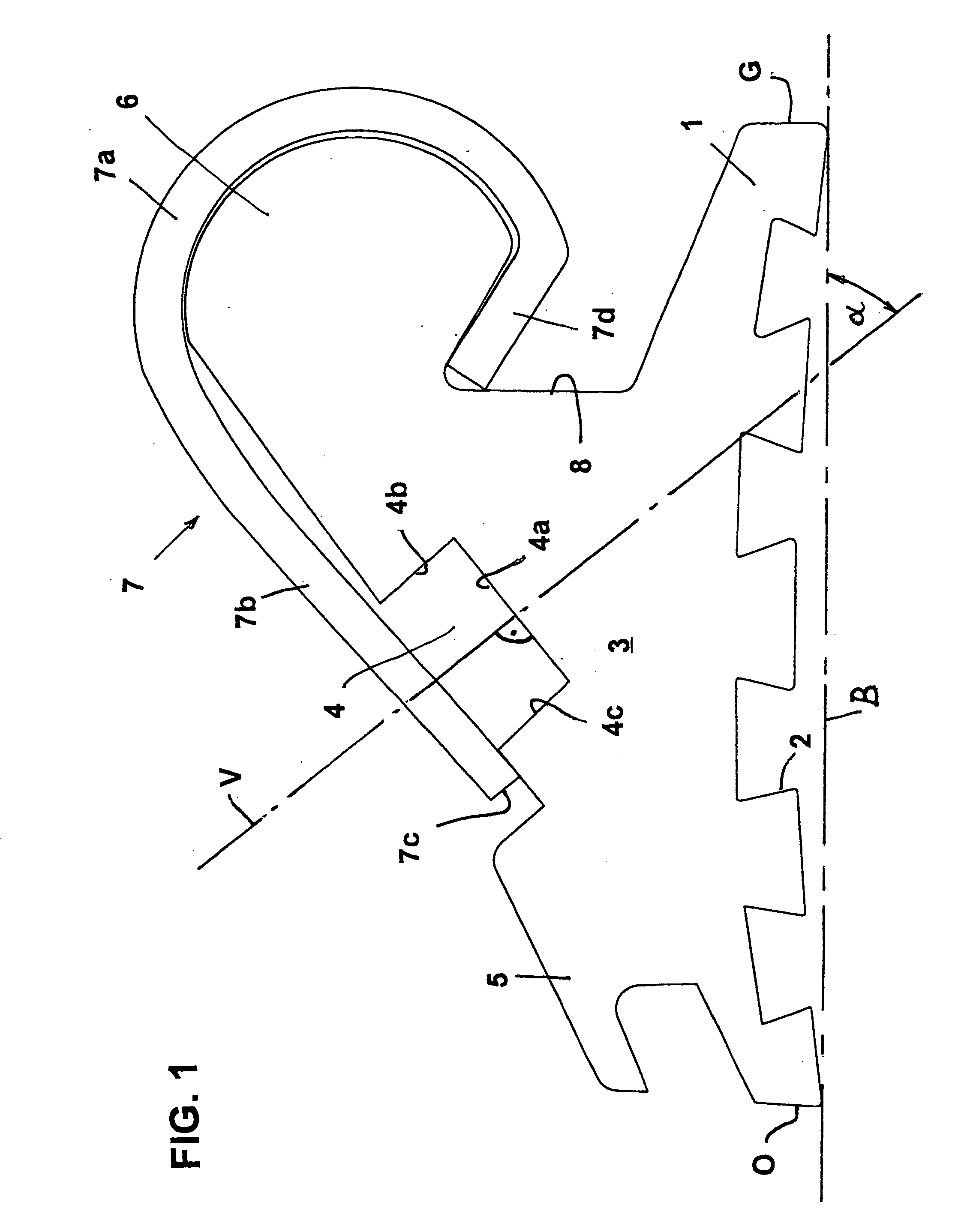
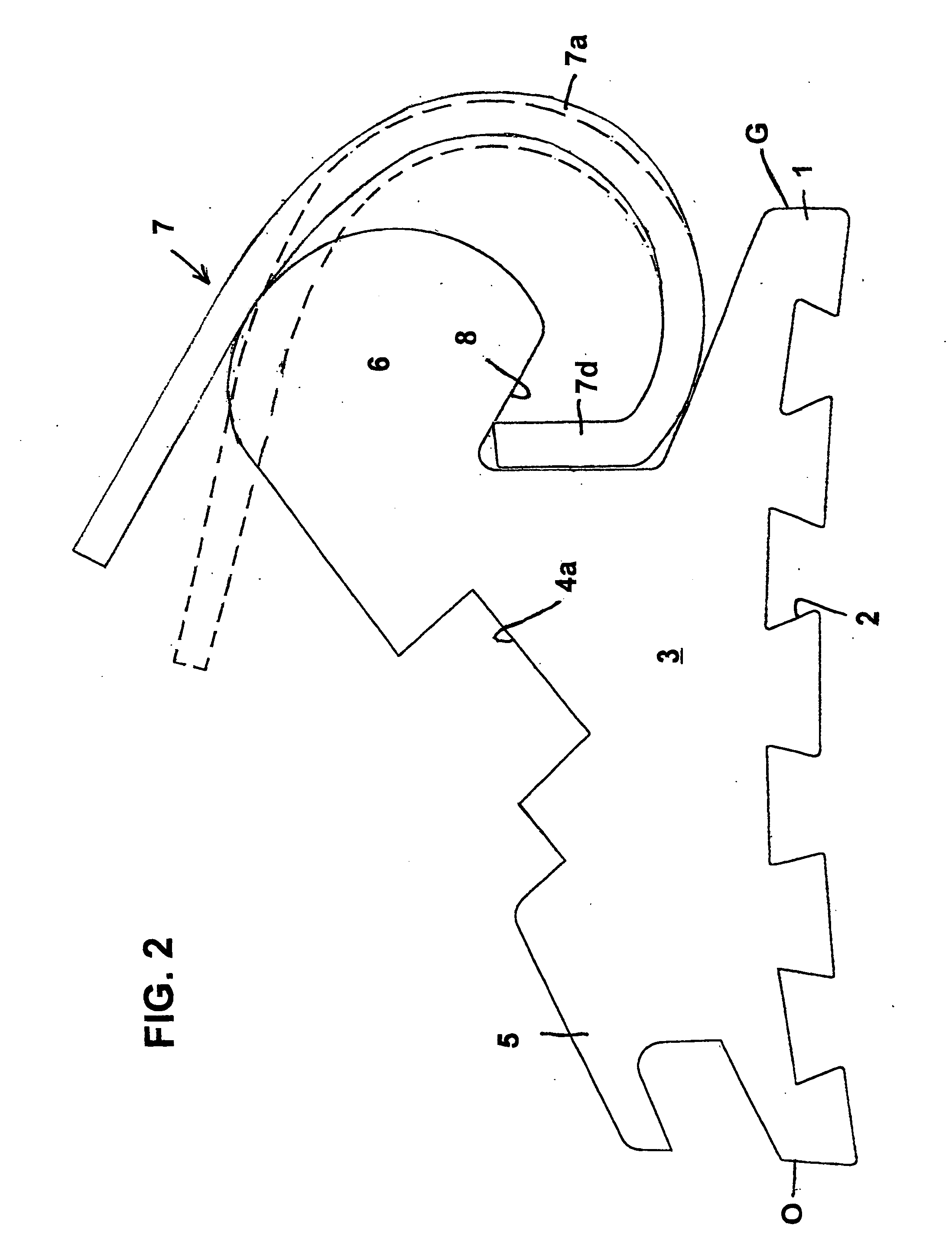
[0037] The bracket according to FIG. 1 consists of a base plate 1 with grooves 2 on its lower side, said grooves having a dovetail-shaped cross section, and of a frame 3 in which a slot 4 of a rectangular cross section is formed. In the example shown, the depth of this slot 4 is smaller than its width. The frame 3 has two wings 5 and 6, which adjoin to the side walls of the slot 4 and which can be used for attaching ligatures. The bracket further includes a spring designated by 7, in this case a leaf spring, which has an arcuate section 7a, which extends over an arc of approximately 270.degree. and which changes over into an approximately straight section 7b, whose end portion covers the slot 54 in the closed condition, as shown in FIG. 1. The arcuate section 7a of the spring encompasses the wing 6 of the frame 3. The spring is held on the frame 3 by its own pre-tension in a state covering the slot 4. The spring 7 may also be a wire strap spring, as it is described in DE 44 07 100 C...


PUM


Abstract

A lingual bracket for orthodontic treatments in the anterior and canine tooth area comprises a slot directed in parallel to the base plate of the bracket, said slot being aligned in a manner that the slot opening points towards the chewing plane. The slot preferably has a depth that is lower than its width. As an element for securing an arch wire in the slot, said slot is preferably covered by a closing spring, which I stably held on the bracket frame in the opening and closing position. An arch wire inserted into the slot is pressed by the closing spring against the slot bottom and generates the forces on the bracket that are required for the tooth position correction. The use of safety lugs for the closing spring can be renounced, which reduces the height of the bracket.

Description

[0001] The present invention refers to a lingual bracket for orthodontic treatments of the upper and lower anterior and canine teeth, consisting of a base plate for the adhesive attachment to the lingual side of a tooth, said base plate having opposing occlusal and gingival edges and opposing mesial and distal edges, a frame elevated from the base plate, said frame having a slot extending substantially in parallel to the occlusal and gingival edges for receiving an arch wire and possibly with a means movably supported at the frame for at least partially covering the slot opening extending in parallel to said edges. A bracket of this kind is known from U.S. Pat. No. 4,698,017.[0002] The teeth of the human denture may have various malalignments. To correct these malalignments, brackets are attached at the teeth, said brackets being connected with one another like pearls on a string by a resilien arch wire inserted into slots provided in the backets, said slots being formed differently...

Claims


Application Information

Patent Timeline
Patent Type & Authority Applications(United States)
IPC IPC(8): A61C7/14A61C7/28A61C7/30
CPCA61C7/145A61C7/30A61C7/285A61C7/28A61C7/12A61C7/14
Inventor HEISER, WOLFGANGSCHENDELL-GROLING, CLAUS
Owner HEISER WOLFGANG
Why Eureka
Try Eureka