Mechanical gear machining device and using method thereof

A processing device and gear technology, applied in the direction of gear tooth manufacturing device, mechanical equipment, metal processing equipment, etc., can solve the problems of relatively high proficiency and skill requirements of workers, high price of large equipment, low product accuracy, etc. Convenience, small footprint and high precision

Inactive Publication Date: 2016-03-30
CHONGQING JIANGJIN HUAMAO MACHINERY CO LTD
View PDF0 Cites 18 Cited by
  • Summary
  • Abstract
  • Description
  • Claims
  • Application Information

AI Technical Summary

Problems solved by technology

[0002] There are various stages in gear machining. First, the rough shape is processed by cutting, and then finishing procedures such as chamfering, deflashing, tooth top chamfering and deburring. At present, many finishing processes such as Operations such as tooth top chamfering still need manual grinding with a grinding machine. This operation method is labor-intensive, and the precision of the product is low, and the operation is complicated. The proficiency and skills of the workers are relatively high, and the efficiency is very low. In order to To solve this problem, many manufacturers will choose to use hobs for processing, but the price of using large-scale equipment is high and the volume is large, which is very uneconomical when the production quantity is relatively small.

Method used


Image

  • Mechanical gear machining device and using method thereof
  • Mechanical gear machining device and using method thereof
  • Mechanical gear machining device and using method thereof

Examples


Embodiment Construction

[0025] The following will clearly and completely describe the technical solutions in the embodiments of the present invention with reference to the accompanying drawings in the embodiments of the present invention. Obviously, the described embodiments are only some, not all, embodiments of the present invention. Based on the embodiments of the present invention, all other embodiments obtained by persons of ordinary skill in the art without making creative efforts belong to the protection scope of the present invention.

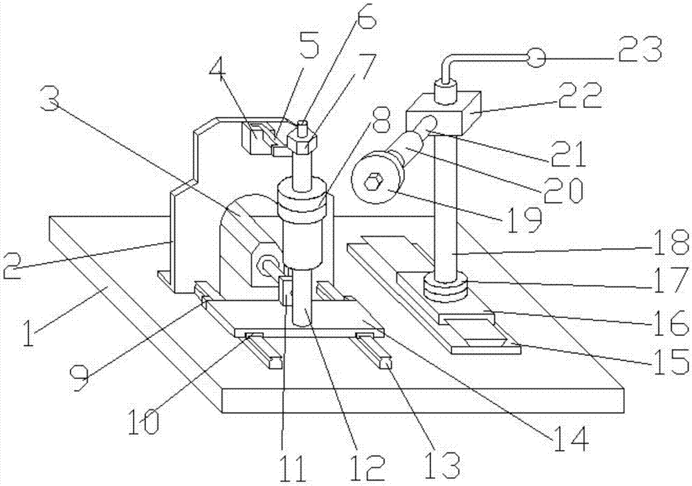
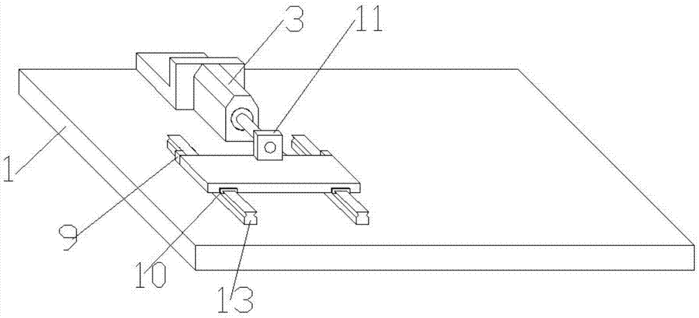
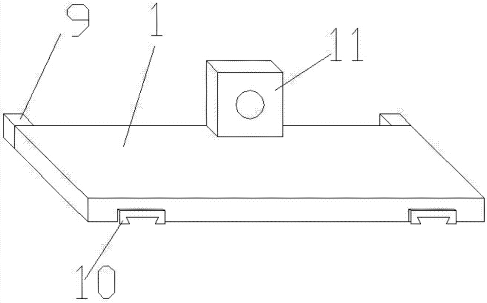
[0026] see Figure 1~4 , a mechanical gear processing device, including a mounting plate 1, a support plate 2, a horizontal cylinder 3, a card slot 4, a brush 5, a pillar 6, a fixing nut 7, a clamp seat 8, a limit block 9, a chute 10, a connecting Block 11, vertical cylinder 12, slide rail 13, slide table 14, guide rail 15, slide seat 16, rotary table 17, fixed column 18, cutter 19, motor 20, adjustment column 21, installation block 22 and control handle 23, i...


PUM


Abstract

The invention discloses a mechanical gear machining device which comprises an installation plate, a supporting plate, a horizontal air cylinder, a clamping groove, a brush, a supporting column, a fixing nut, a clamping seat, limiting blocks, a sliding groove, a connection block, a vertical air cylinder, sliding rails, a sliding table, a guide rail, a sliding seat, a rotary table, a fixed column, a tool, a motor, an adjusting column, an installation block and an operation handle. The mechanical gear machining device has the beneficial effects that gear chamfering, tooth crest chamfering and the like can be conducted in a multi-angle mode; the sliding table can slide on the sliding rails under the traction of the horizontal air cylinder, and the tool can conduct multi-face machining on a gear conveniently during machining; the two rubber limiting blocks are fixed to the side edges, close to the supporting plate, of the sliding table, so that the sliding table is prevented from knocking into the supporting plate during movement; the brush is a wire brush and can be detached freely from the interior of the clamping groove, and deburring treatment can be conducted on the gear through the wire brush; the position of the installation block can be adjusted up and down on the fixed column, and specific adjustment can be conducted on gears of different specifications.

Description

technical field [0001] The invention relates to gear processing equipment, in particular to a mechanical gear processing device and a method for using the same, belonging to the field of mechanical equipment processing. Background technique [0002] There are various stages in gear machining. First, the rough shape is processed by cutting, and then finishing procedures such as chamfering, deflashing, tooth top chamfering and deburring. At present, many finishing processes such as Operations such as tooth top chamfering still need manual grinding with a grinding machine. This operation method is labor-intensive, and the precision of the product is low, and the operation is complicated. The proficiency and skills of the workers are relatively high, and the efficiency is very low. In order to To solve this problem, many manufacturers will choose to use hobs for processing, but the price of using large-scale equipment is high and the volume is large, which is very uneconomical w...

Claims


Application Information

Patent Timeline
Patent Type & Authority Applications(China)
IPC IPC(8): B23F19/10B23F19/00B23F23/06
CPCB23F19/10B23F19/00B23F23/06
Inventor 傅茂兰
Owner CHONGQING JIANGJIN HUAMAO MACHINERY CO LTD
Why Eureka
Try Eureka