Leading edge protector

a leading edge and protector technology, applied in the field of protectors, can solve the problems of small fragments releasing, and achieve the effects of reducing or avoiding energy transmission along the leading edge through the formers, efficient damping, and facilitating the use of a given protector segmen

Inactive Publication Date: 2015-08-06
ROLLS ROYCE PLC
View PDF6 Cites 17 Cited by
  • Summary
  • Abstract
  • Description
  • Claims
  • Application Information

AI Technical Summary

Benefits of technology

[0019]Conveniently, each protector segment may further include a former which defines the external shape of the component at the leading edge, the sheath of the protector segment wrapping around the former. The former may be produced of a different material to the sheath, for example the former may be produced of a polymer or a polymer matrix composite. Such a material can be formed e.g. by resin transfer moulding, compression or injection moulding, or resin infusion. However, other materials options for the former are possible. The former can be bullet-shaped on a cross-section through the component perpendicular to the leading edge, i.e. with the tip of the bullet at the leading edge. Spaced side plates of the sheath may extend rearwardly from the former over the air-washed surfaces of the component. Although the sheaths of neighbouring protector segments overlap, a clearance gap can be provided between the formers of succeeding protector segments. In this way, under impact, the formers can be prevented from hitting each other, and energy transmission along the leading edge through the formers can be reduced or avoided. The clearance gap can be filled with air, or a material having a lower density than the material of the formers, such as metallic or polymer foam, or rubber. More generally, the material filling the clearance gap can be any material that is capable of providing efficient damping (whether by elastic compression, friction or other means) between the formers.
[0020]The overlap between each pair of neighbouring sheaths can be produced by an insertion portion of one sheath which inserts inside an overlying portion of the other sheath. Conveniently, each sheath can have an insertion portion at one end thereof and an overlying portion at the other end thereof. This facilitates the use of a given protector segment at different positions along the leading edge. Each insertion portion can be formed by a reduced width region in which the distance between opposing sides of the respective sheath is decreased.

Problems solved by technology

Furthermore, in the event of a high energy impact event, smaller fragments will tend to be released.

Method used


Image

  • Leading edge protector
  • Leading edge protector
  • Leading edge protector

Examples


Embodiment Construction

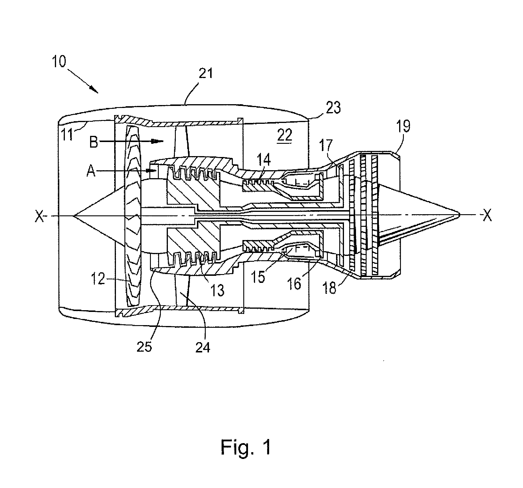
[0032]With reference to FIG. 1, a ducted fan gas turbine engine incorporating the invention is generally indicated at 10 and has a principal and rotational axis X-X. The engine comprises, in axial flow series, an air intake 11, a propulsive fan 12, an intermediate pressure compressor 13, a high-pressure compressor 14, combustion equipment 15, a high-pressure turbine 16, an intermediate pressure turbine 17, a low-pressure turbine 18 and a core engine exhaust nozzle 19. A nacelle 21 generally surrounds the engine 10 and defines the intake 11, a bypass duct 22 and a bypass exhaust nozzle 23. The bypass duct 22 contains a row of outlet guide vanes 24.

[0033]During operation, air entering the intake 11 is accelerated by the fan 12 to produce two air flows: a first air flow A into the intermediate pressure compressor 13 and a second air flow B which passes through the bypass duct 22 to provide propulsive thrust. The two air flows A and B divide from each other at an annular splitter fairin...


PUM


Abstract

A component of a gas turbine engine is provided. The component has a leading edge with two air-washed surfaces extending rearwardly therefrom to define opposing sides of the component, The component has a leading edge protector formed as a plurality of protector segments which succeed in a line along the leading edge. Each protector segment includes a sheath which covers the leading edge and the air-washed surfaces at regions adjacent the leading edge. Each protector segment overlaps with the neighbouring sheath of the succeeding segment.

Description

FIELD OF THE INVENTION[0001]The present invention relates to a protector for a leading edge of a component of a gas turbine engine, such as an aerofoil component.BACKGROUND OF THE INVENTION[0002]Within gas turbine engines the leading edges of rotating and stationary aerofoils and of other components are subject to high levels of erosion and impact loading. In particular the fart blades and their subsequent guide vanes can experience harsh abrading environments including dust, sand, ice and water. They can also suffer impacts from foreign bodies such as birds and debris. Therefore the leading edges need to be sufficiently resistant to withstand such environments and impacts.[0003]In respect of a metallic component, the metal of component itself may be sufficiently resistant, or a surface coating can be added that improves resistance. However, in general, polymer matrix composite materials, such as sometimes are used to form fan blades and guide vanes, are not sufficiently resistant t...

Claims


Application Information

Patent Timeline
Patent Type & Authority Applications(United States)
IPC IPC(8): F01D5/28F01D9/02
CPCF01D5/147F01D5/286F01D9/041F04D29/289F04D29/324F05D2220/36F05D2240/121F05D2240/303F01D5/282F01D9/02F04D29/542Y02T50/60
Inventor BOTTOME, KRISTOFER JOHN
Owner ROLLS ROYCE PLC
Why Eureka
Try Eureka