Damping arrangement for a blade of an axial turbine

a technology of axial turbine and blade, which is applied in the direction of liquid fuel engines, vessel construction, marine propulsion, etc., can solve the problems of only providing special damping elements, affecting the vibration of blade aerofoils, and limiting the proposal to special damping elements, so as to achieve simple construction and effective

Inactive Publication Date: 2007-11-27
ALSTOM TECH LTD
View PDF10 Cites 22 Cited by
  • Summary
  • Abstract
  • Description
  • Claims
  • Application Information

AI Technical Summary

Benefits of technology

[0011]One of numerous aspects of the present invention is, therefore, providing a damping arrangement for blades of axial turbines, which damping arrangement is simple in construction, effective in action and effective over a large region of the blade aerofoil.
[0012]Another aspect of the present invention includes accommodating the damping element of the damping arrangement in a recess, which is configured as a cavity extending in the radial direction through the inside of the blade aerofoil, into which cavity the damping element is inserted in the radial direction. Due to the cavity which extends in the radial direction and into which the damping element is introduced in the radial direction, the outer contour of the blade aerofoil remains uninfluenced by the damping appliance. Because the cavity extends over wide segments of the blade aerofoil, the vibrations can be very effectively damped over the whole of the blade aerofoil.
[0013]An exemplary embodiment of the invention is characterized in that the cavity and the damping element inserted into the cavity have cylindrical configurations. By this means, the manufacture and installation of the damping device are further simplified.
[0014]A first development of the invention is characterized in that the damping element is configured in such a way that the frictional damping process takes place within the damping element, the damping element preferably containing a damping medium, in particular in the form of a highly viscous fluid. In contrast to the known state of the art (see W0-A1-01 / 49975), the element which contains the damping medium can be manufactured separately from the blade in a simple manner and can be very easily introduced into the blade.

Problems solved by technology

During the operation of the turbine, the blades are excited to vibrate by the interaction with the medium flowing at high velocity through the turbine and by the rapid rotation; loads are imposed on the blades and bearings and have a disadvantageous effect on the efficiency.
Some of these proposals are limited to providing special damping elements in the region of the blade fastening.
Although this has the advantage that no modifications have to be undertaken on the blade aerofoil itself, it has the disadvantage that vibrations in the blade aerofoil can only be influenced very indirectly.
Disadvantageous features of this known damping arrangement are the complicated construction of the pocket and pocket cover and the spatial limitation of the damping arrangement to a very small region of the blade aerofoil.
This solution also requires complicated and accurate processing of the individual elements of the damping device and only permits locally limited damping.
This has, due to the viscosity of the moving air, a damping effect on the blade vibrations which occur.
This type of damping is not very flexible and likewise requires complicated and accurate processing and / or reworking of the blade surface in order to avoid aerodynamic disadvantages due to the installation of the damping device.
Summarizing in the case of the solutions mentioned above, it can be stated, on the one hand, that complicated and careful machining is necessary because of the action on the aerodynamically important blade surface and, on the other, that damping can only be realized in narrowly limited regions.

Method used


Image

  • Damping arrangement for a blade of an axial turbine
  • Damping arrangement for a blade of an axial turbine
  • Damping arrangement for a blade of an axial turbine

Examples


Embodiment Construction

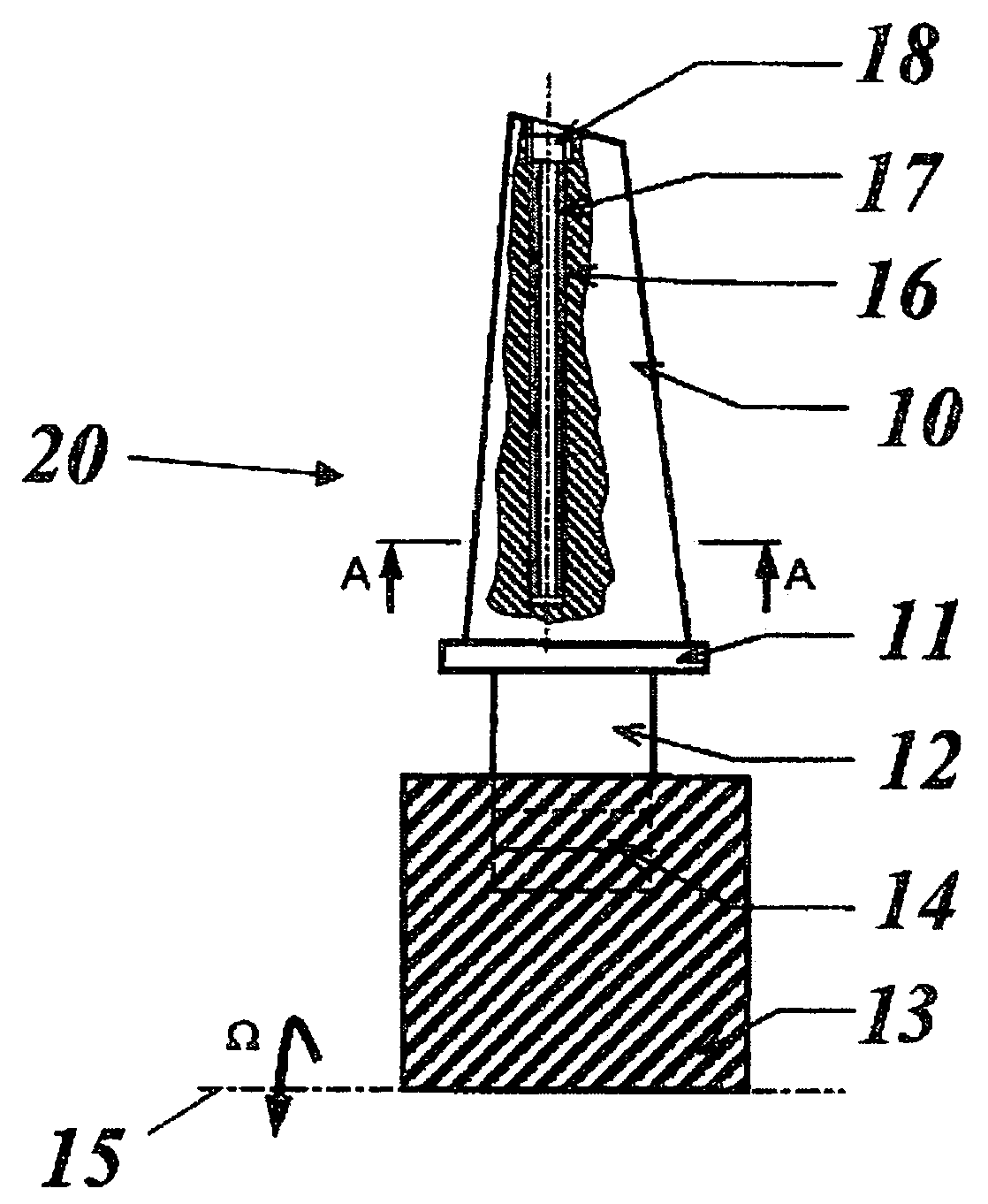
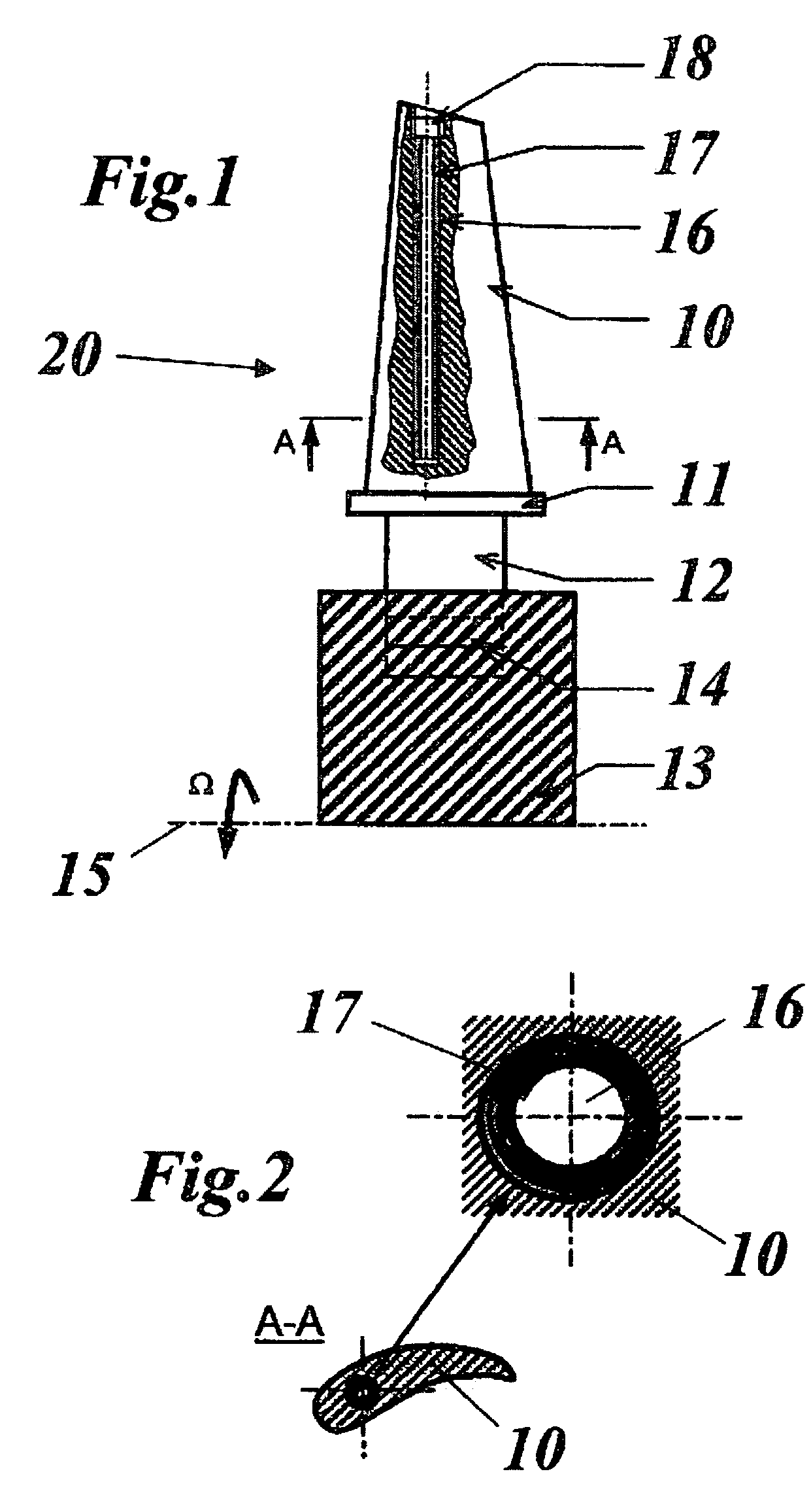
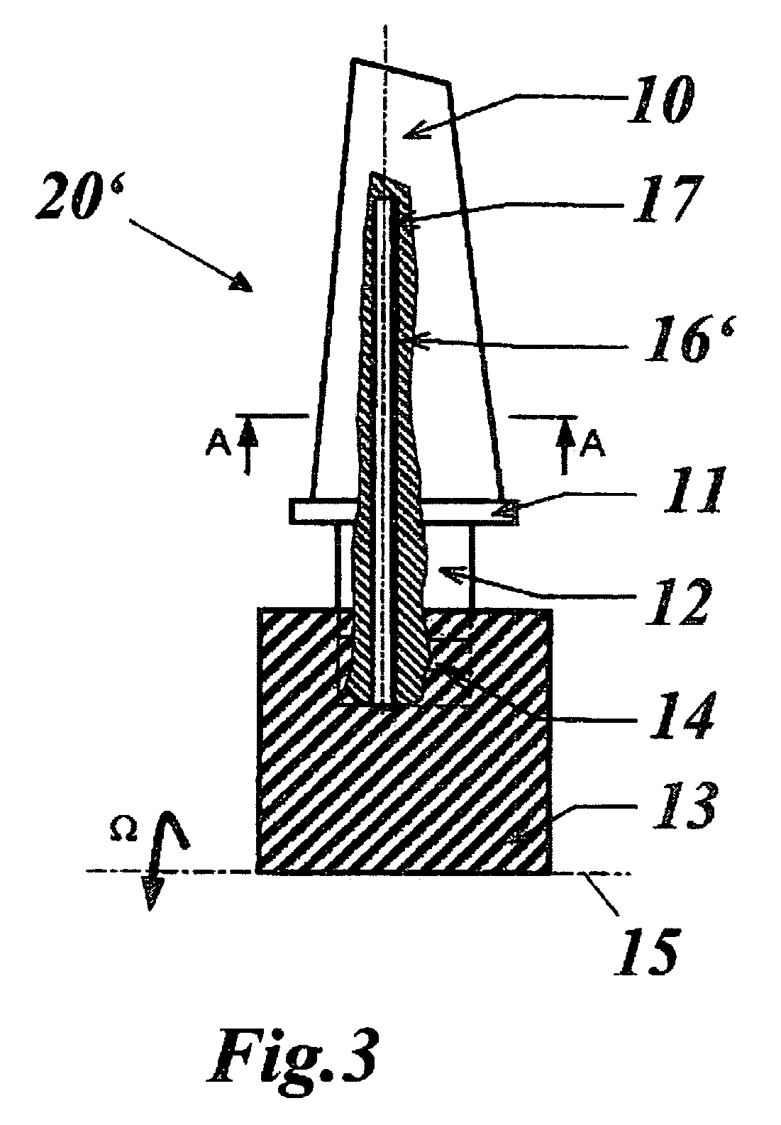
[0022]The present invention relates to a blade arrangement with a damping appliance. As shown in FIG. 1, a blade 20 is mounted as an axial blade at the periphery of a rotor section 13 of a rotor rotating with an angular velocity Ω about a rotor axis 15, the blade 20 extending in the radial direction. The blade 20 comprises, sequentially in the radial direction from the inside to the outside, a stem 12, a platform 11 and the actual blade aerofoil 10. The blade 20 is inserted into an appropriate recess in the rotor section 13 by means of a usually fir-tree shaped blade root 14 at the bottom end of the stem 12. The blade aerofoils 10 of the blades of a turbine stage arranged in a ring around the rotor axis 15 can either have a free-standing configuration or be connected together at the blade tips by a shroud, a damping device or a lacing wire.

[0023]Extending in the radial direction, each blade 20 has a cylindrical cavity 16 which is arranged within the blade aerofoil 10. From the blade...


PUM


Abstract

A damping arrangement for a blade (20) of an axial turbine, in particular a gas turbine, includes a damping element (17) which is arranged in a recess (16) in the blade aerofoil (10) of the blade (20) and frictionally dampens the vibrations of the blade (20). In such a damping arrangement, simplified manufacture and assembly and a reliable and effective function are achieved by the recess being configured as a cavity (16) extending in the radial direction through the inside of the blade aerofoil (10), the damping element (17) being inserted in the radial direction into said cavity (16).

Description

[0001]This application claims priority under 35 U.S.C. § 119 to German application number 103 56 237.0, filed 2 Dec. 2003, the entirety of which is incorporated by reference herein.BACKGROUND OF THE INVENTION[0002]1. Field of the Invention[0003]The present invention relates to the field of turbine technology. It concerns a damping arrangement for a blade of an axial turbine.[0004]2. Brief Description of the Related Art[0005]The rotor blades of axial turbines, for example gas turbines, extend in the radial direction and are mounted on the outer periphery of the rotor which rotates about the rotor axis. They can be configured as free-standing blade aerofoils in a turbine stage but can also be connected to one another on their outer periphery by a shroud, a snubber or a lacing wire.[0006]During the operation of the turbine, the blades are excited to vibrate by the interaction with the medium flowing at high velocity through the turbine and by the rapid rotation; loads are imposed on th...

Claims


Application Information

Patent Timeline
Patent Type & Authority Patents(United States)
IPC IPC(8): F01D5/16F01D5/26
CPCF01D5/16F01D5/26Y02T50/673Y02T50/60
Inventor MASSEREY, PIERRE-ALAINSZWEDOWICZ, DARIUSZSZWEDOWICZ, JAROSLAW
Owner ALSTOM TECH LTD
Why Eureka
Try Eureka