
Handle assembly for power tool

a technology for power tools and parts, applied in the direction of manufacturing tools, portable percussive tools, portable power-driven tools, etc., can solve the problems of increasing the cost and complexity of hammer drill manufacturing, and achieve the effect of simplifying assembly construction

Active Publication Date: 2009-07-30
BLACK & DECKER INC
View PDF9 Cites 23 Cited by
  • Summary
  • Abstract
  • Description
  • Claims
  • Application Information

AI Technical Summary

Benefits of technology

The present invention provides a handle assembly for a power tool with a mounting part that can be easily attached to the housing of the tool, and a fastening mechanism for tightening and loosening the mounting part. The assembly also includes at least one vibration damping member to damp vibrations transmitted from the housing to the handle. The vibration damping member can be a flexible band or a support, and a fastening member or a locking member can be used to tighten or loosen the mounting part. The assembly is designed to be compact and effective in damping vibrations, and can be easily assembled and disassembled.

Problems solved by technology

However, this arrangement suffers from the drawback that significant vibrations can still be transmitted from the housing to the grip portion, and a separate tensioning part is required to tighten or loosen the strap retainer, which increases the cost and complexity of manufacture of the hammer drill.

Method used


Image

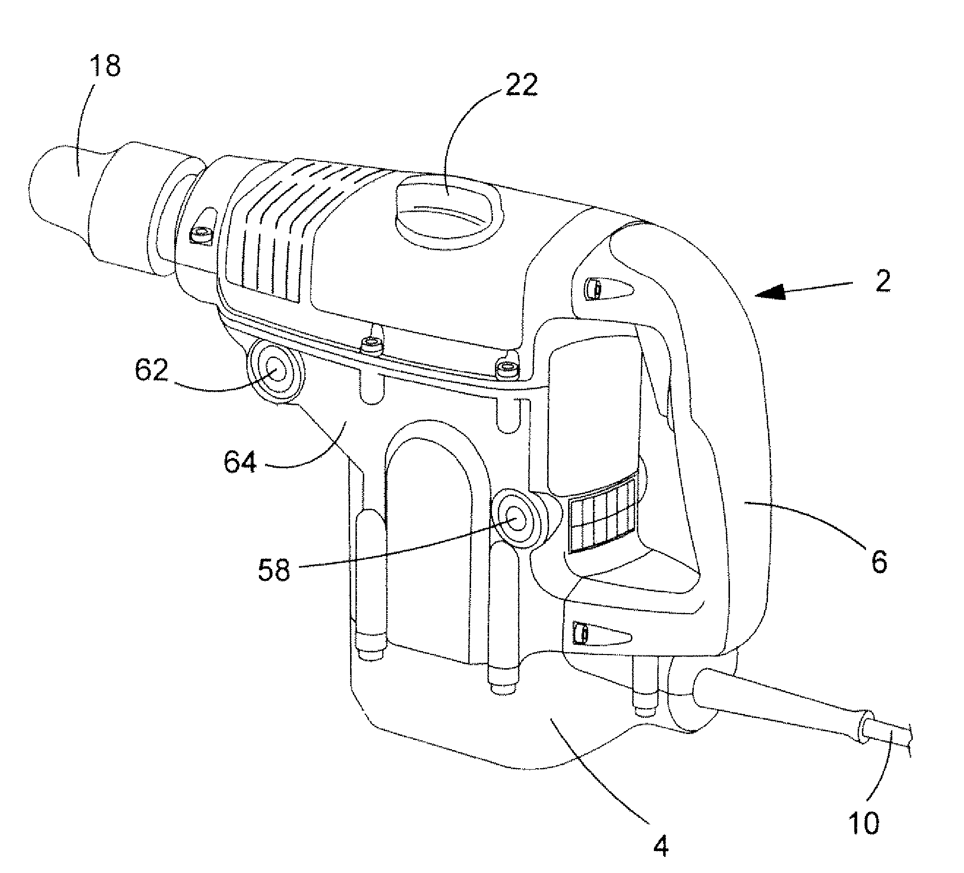
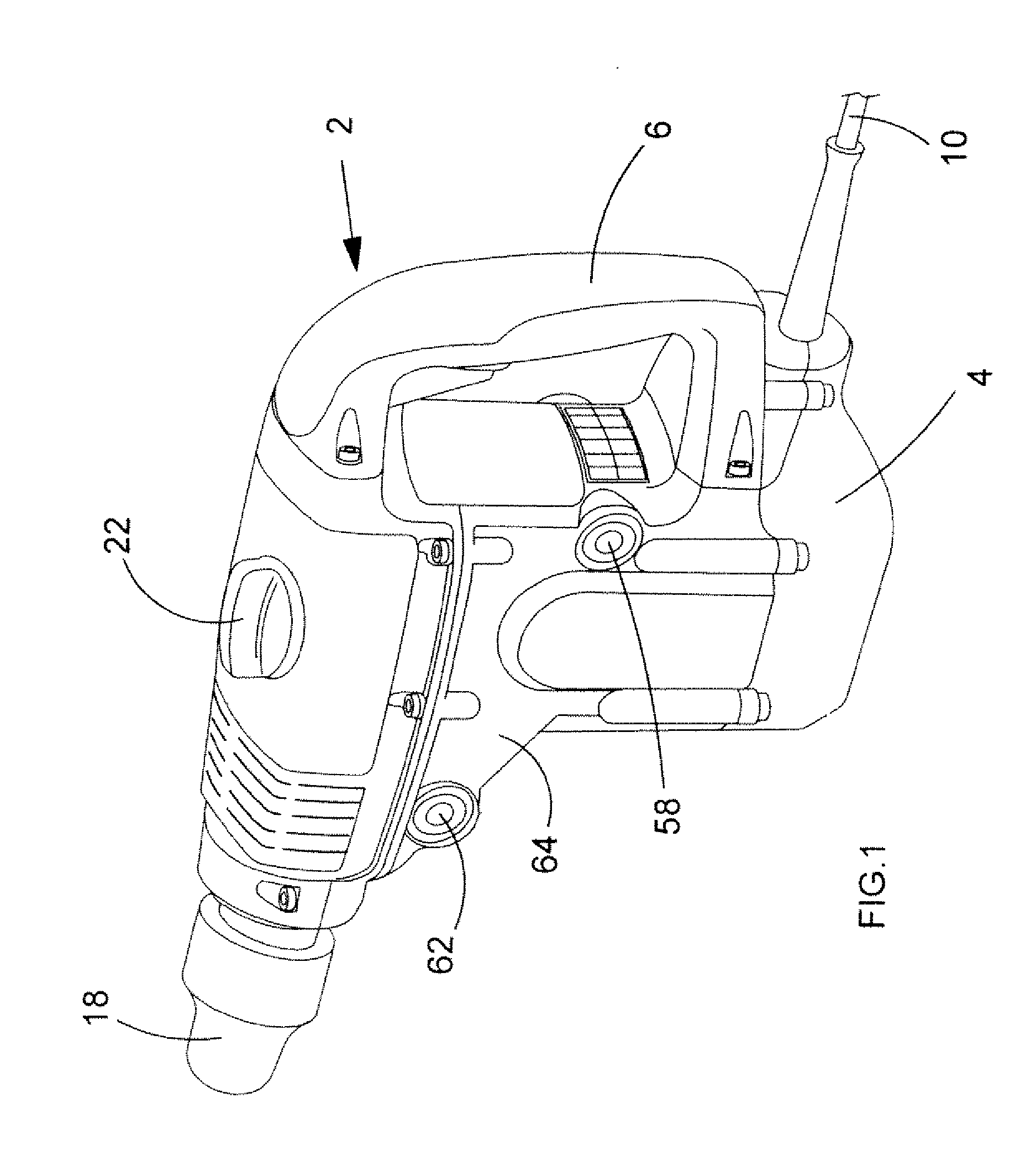
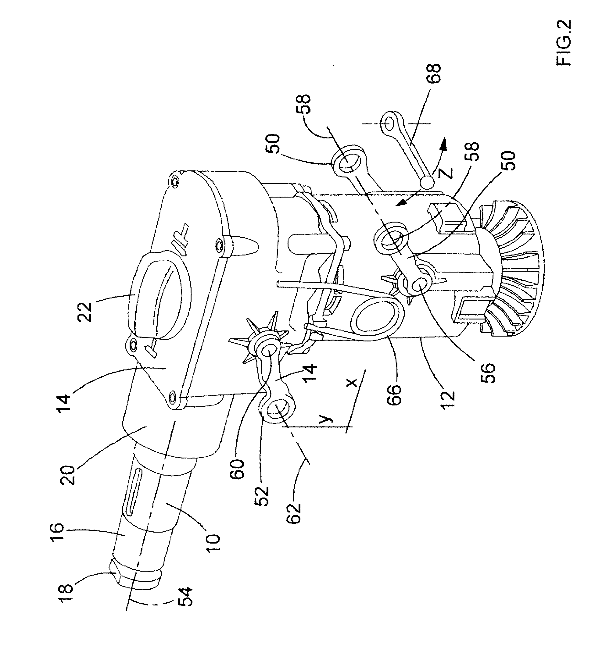
  • Handle assembly for power tool
  • Handle assembly for power tool
  • Handle assembly for power tool

Examples


second embodiment

[0102]a side handle assembly embodying the present invention is shown in FIG. 14, in which pairs of resilient vibration damping members 152 are provided in the recesses 150 in the support 100. Similar vibration damping members (not shown) can be provided in the recesses 138 on the flange 136 of the handle 84.

third embodiment

[0103]a side handle assembly embodying the present invention is shown in FIG. 15, in which pairs of resilient vibration damping members 154 are provided on the first and second pegs 142, 146 on the locking ring 140.

fourth embodiment

[0104]a side handle assembly embodying the present invention is shown in FIG. 16, in which a strip 156 of resilient material is provided on the inner surface of the metal strip 82, in order to damp vibrations transmitted from the outer housing 4 of the hammer drill 2 to the metal strip 82.

[0105]Overload Clutch Assembly

[0106]A known two torque clutch connected between a motor output shaft and a spindle drive of the hammer drill of FIG. 1 is disclosed in WO 2004 / 024398. A similar clutch will now be described in more detail with reference to FIGS. 17 to 19.

[0107]A bevel gear 158 which forms part of the clutch arrangement is integrally formed with a shaft 160 of circular cross section. The upper end of the shaft 160 is rotatably mounted within the housing 4 of the hammer via a bearing comprising an inner race 162 which is rigidly attached to the shaft 160, an outer race 164 which is rigidly attached to the housing and ball bearings 166 which allow the outer race 164 to freely rotate abo...


PUM

PropertyMeasurementUnit
flexibleaaaaaaaaaa
vibration dampingaaaaaaaaaa
resilientaaaaaaaaaa

Abstract

A handle assembly for a power tool is disclosed. The handle assembly has a handle (84), a metal strip (82) for releasably mounting the handle assembly to the housing of a power tool, and a fastening mechanism (80, 100, 104) for tightening and loosening the metal strip on the housing of the power tool. Vibration dampers (124, 126) are located between the handle and the fastening mechanism to damp vibrations transmitted from the fastening mechanism to the handle. Limited rotation of the handle relative to the metal strip is possibly, but rotation beyond predetermined limits causes the fastening mechanism to tighten and / or loosen the metal strip on the housing.

Description

CROSS-REFERENCE TO RELATED APPLICATIONS[0001]This application claims priority, under 35 U.S.C. §119(a)-(d), to UK Patent Application No. GB 08 013 02.1 filed Jan. 24, 2008, the contents thereof to be incorporated herein by reference in its entirety.FIELD OF THE INVENTION[0002]The present invention relates to handle assemblies for power tools, and relates particularly, but not exclusively, to removable handle assemblies for hammer drills.BACKGROUND OF THE INVENTION[0003]Power tools such as hammer drills are known which have a housing defining a rear handle at a rear part of the housing, and a side handle assembly having a mounting portion releasably mounted to a forward part of the housing. A grip portion coupled to the mounting portion, which allows the user to grip the power tool with both hands, and the side handle assembly is removably mounted for left or right handed use. Known handle assemblies include vibration damping means to damp vibrations transmitted from a main spindle o...

Claims


Application Information

Patent Timeline
Patent Type & Authority Applications(United States)
IPC IPC(8): B25D17/04
CPCB25D17/043B25D17/24B25D2216/0084B25D2222/57B25F5/003B25D2250/255B25F5/006B25F5/026B25D2250/165
Inventor HAHN, NORBERT
Owner BLACK & DECKER INC
Learn More