
Damping device for a gas turbine, gas turbine and method for damping thermoacoustic oscillations

a technology of thermoacoustic oscillation and damping device, which is applied in the direction of instruments, lighting and heating apparatus, machines/engines, etc., can solve the problems of reducing affecting the performance of the helmholtz resonator, etc., to achieve the effect of damping thermoacoustic oscillation

Inactive Publication Date: 2016-01-07
SIEMENS AG
View PDF4 Cites 23 Cited by
  • Summary
  • Abstract
  • Description
  • Claims
  • Application Information

AI Technical Summary

Benefits of technology

The invention involves a configuration where a duct is used to cool down the transmission medium. In this configuration, the duct can also be purged with purging air to increase the cooling effect. However, the duct can also cool down the transmission medium without the need for purging air.

Problems solved by technology

Such thermoacoustic oscillations, which arise in particular in the combustion chamber of the gas turbine, may lead to considerable damage to the components during operation of the gas turbine and force shutdown of the installation.
A disadvantage of this method is that the performance of the Helmholtz resonator reduces as the velocity of the purging air in the damping pipe increases.
The compressor air used for purging is also not available as combustion air, which has a disadvantageous effect on the emission values achieved by the gas turbine.

Method used


Image

  • Damping device for a gas turbine, gas turbine and method for damping thermoacoustic oscillations
  • Damping device for a gas turbine, gas turbine and method for damping thermoacoustic oscillations
  • Damping device for a gas turbine, gas turbine and method for damping thermoacoustic oscillations

Examples


Embodiment Construction

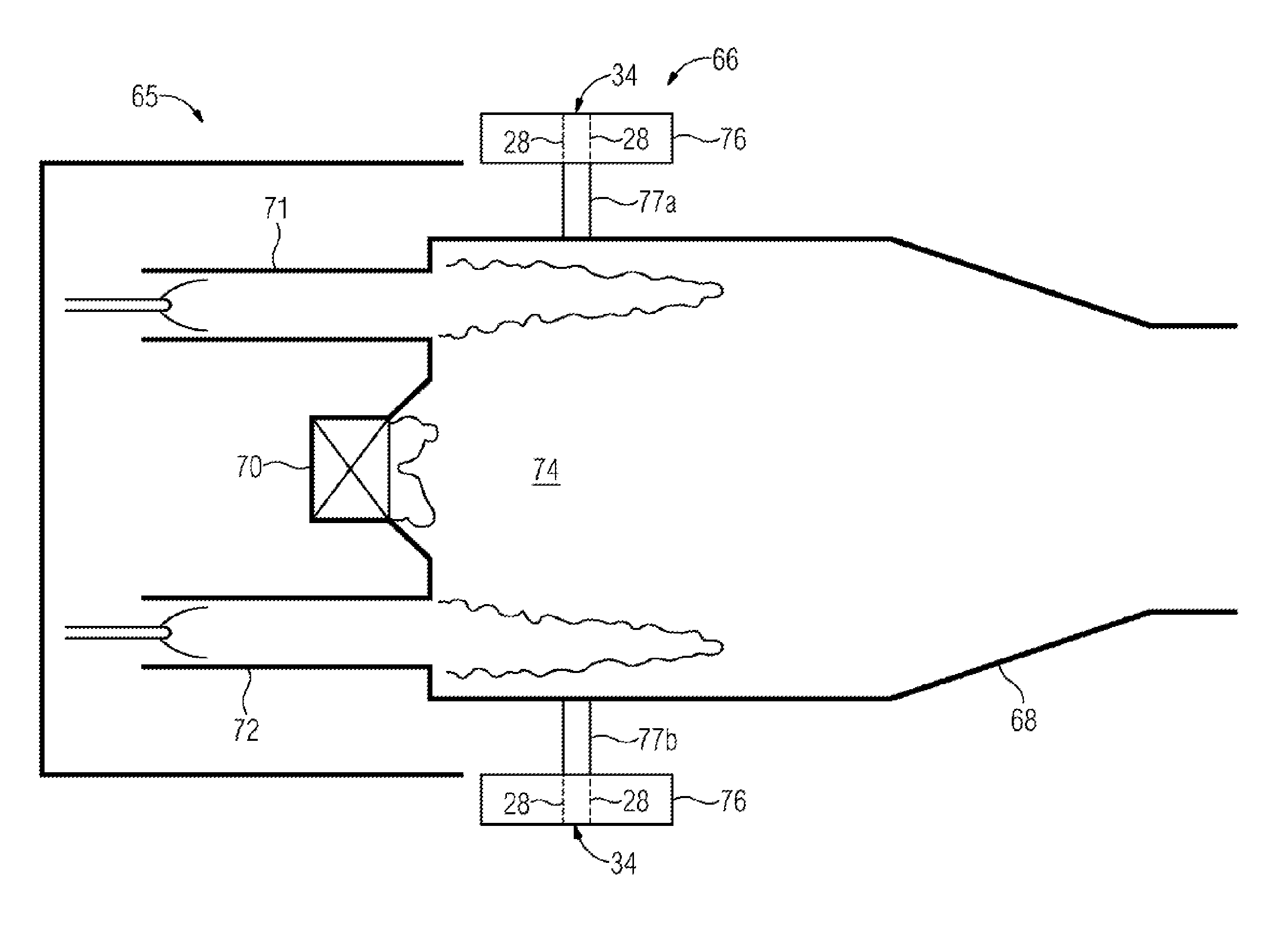
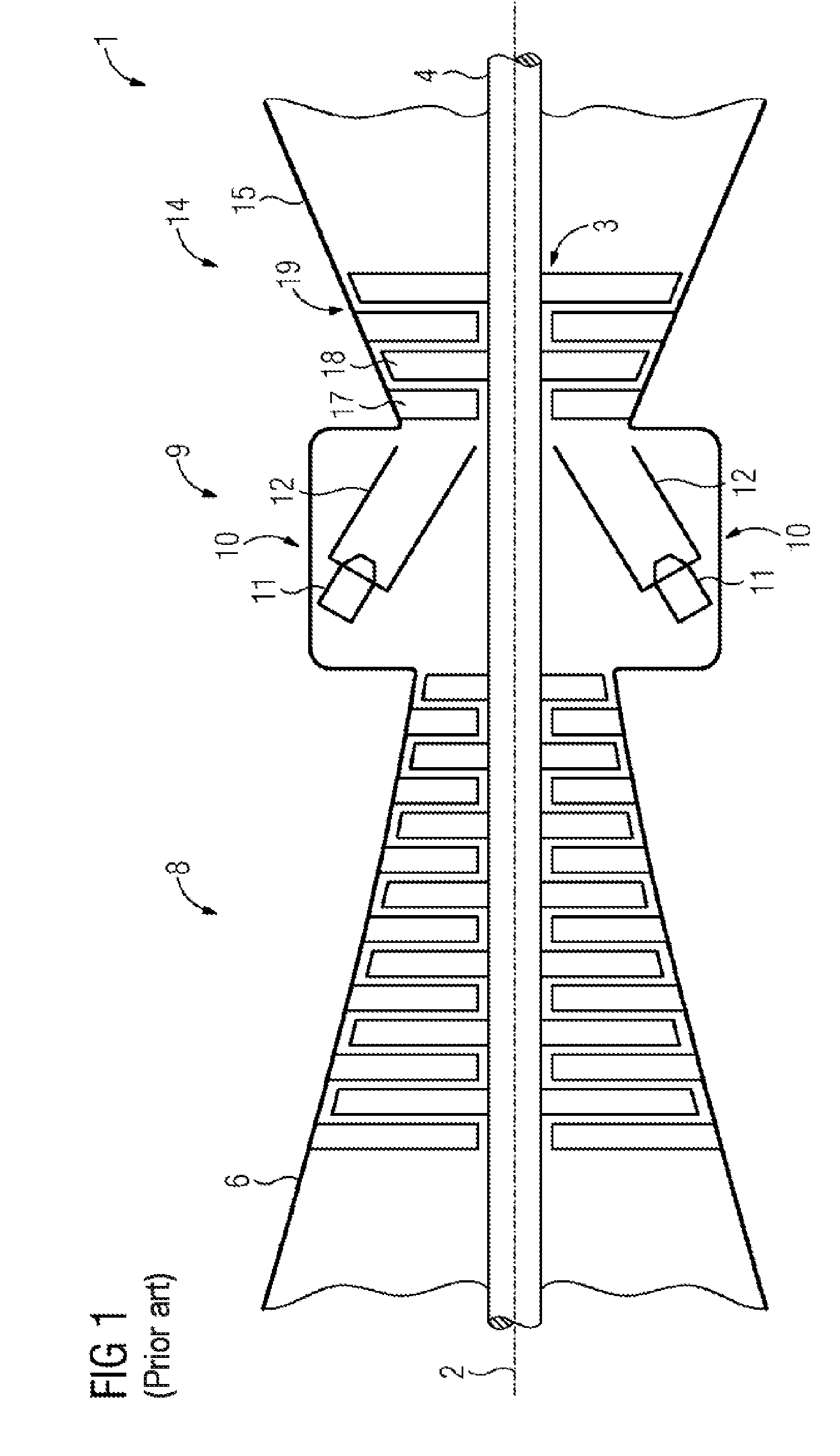
[0081]FIG. 1 shows a sectional view of a gas turbine 1 according to the prior art in a schematically simplified representation. In its interior, the gas turbine 1 comprises a rotor 3 mounted so as to rotate about an axis of rotation 2 and having a shaft 4, said rotor also being known as a turbine wheel. The following succeed one another along the rotor 3: an intake housing 6, a compressor 8, a combustion system 9 with a number of tubular combustion chambers 10, which each comprise a burner arrangement 11 and a housing 12, a turbine 14 and a waste gas housing 15.

[0082]The combustion system 9 communicates with a for example annular hot gas duct. A plurality of series-connected turbine stages there form the turbine 14. Each turbine stage is formed of rings of blades or vanes. When viewed in the direction of flow of a working medium, a row formed of guide vanes 17 follows a row of rotor blades 18 in the hot duct. The guide vanes 17 are here fastened to an inner housing of a stator 19, w...


PUM


Abstract

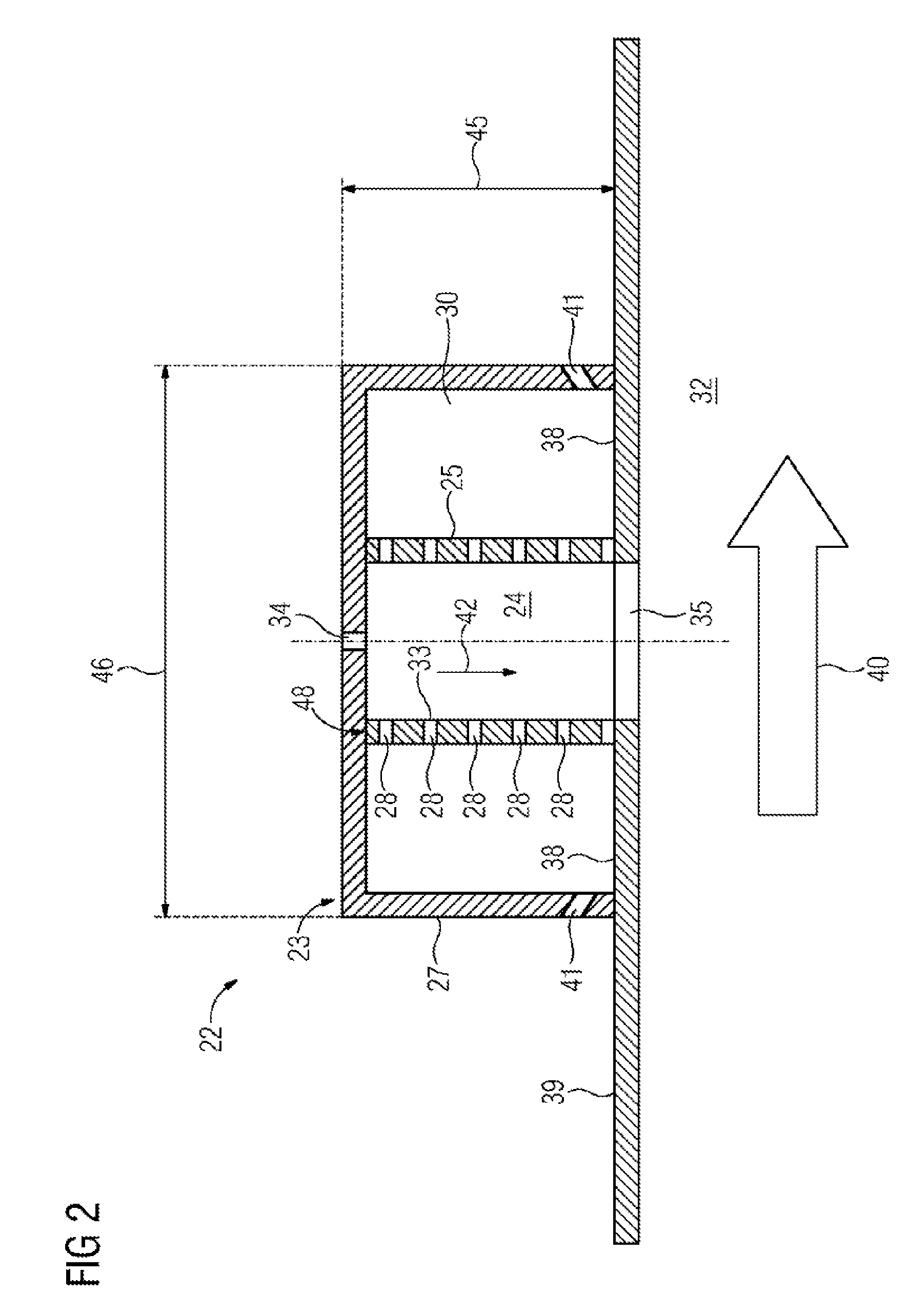
A damping device for a gas turbine has at least one Helmholtz resonator and at least one duct, wherein the Helmholtz resonator has a resonator housing and at least one resonator neck pipe and the resonator housing encloses a resonance volume of the Helmholtz resonator, into which volume acoustic vibrations can be injected by means of the resonator neck pipe. The damping device enables a particularly effective damping of thermo-acoustic vibrations. For this purpose, the duct is formed with a duct jacket and at least one outlet opening. Acoustic vibrations of a fluid stream flowing through a burner plenum and a combustion chamber can be injected into the outlet opening. A cooling fluid can be applied to the duct and the at least one resonator neck pipe opens on the hot-gas side into such a duct upstream of the at least one outlet opening.

Description

CROSS REFERENCE TO RELATED APPLICATIONS[0001]This application is the US National Stage of International Application No. PCT / EP2014 / 053921 filed Feb. 28, 2014, and claims the benefit thereof. The International Application claims the benefit of European Application No. EP13157106 filed Feb. 28, 2013. All of the applications are incorporated by reference herein in their entirety.FIELD OF INVENTION[0002]The invention relates to a damping device for a gas turbine with at least one Helmholtz resonator and at least one duct with duct jacketing. The Helmholtz resonator comprises a resonator housing and at least one resonator neck tube, wherein the resonator housing encloses a resonance volume of the Helmholtz resonator into which acoustic oscillations may be injected by means of the resonator neck tube. The duct comprises at least one outlet orifice. The invention also relates to a gas turbine having at least one combustion chamber and at least one such damping device and to a method for da...

Claims


Application Information

Patent Timeline
Patent Type & Authority Applications(United States)
IPC IPC(8): F02C7/24F02C3/04F02C7/18F23R3/00
CPCF02C7/24F23R3/005F05D2260/963F02C3/04F05D2220/32F02C7/18F23R3/002F23R2900/00014F23M20/005G10K11/172
Inventor BECK, CHRISTIANVAN KAMPEN, JAAP
Owner SIEMENS AG
Learn More