Damping electromagnetic oscillations in power systems

a technology of electromagnetic oscillation and power system, applied in pulse manipulation, pulse technique, instruments, etc., can solve the problems of insufficient damped oscillation, insufficient damped oscillation, and insufficient damped oscillation of power system operating poin

a technology of electromagnetic oscillation and power system, applied in pulse manipulation, pulse technique, instruments, etc., can solve the problems of insufficient damped oscillation, insufficient damped oscillation, and insufficient damped oscillation of power system operating poin

US20100023179A1Inactive Publication Date: 2010-01-28ABB POWER GRIDS SWITZERLAND AG +1

Image

  • Damping electromagnetic oscillations in power systems
  • Damping electromagnetic oscillations in power systems
  • Damping electromagnetic oscillations in power systems

Examples


Embodiment Construction

[0024]Exemplary embodiments of the present disclosure damp multiple electromagnetic oscillations in electric power transmission networks in a flexible manner and with minimal additional equipment. Exemplary embodiments provide a method and a controller for damping multiple electromagnetic oscillations in a power system.

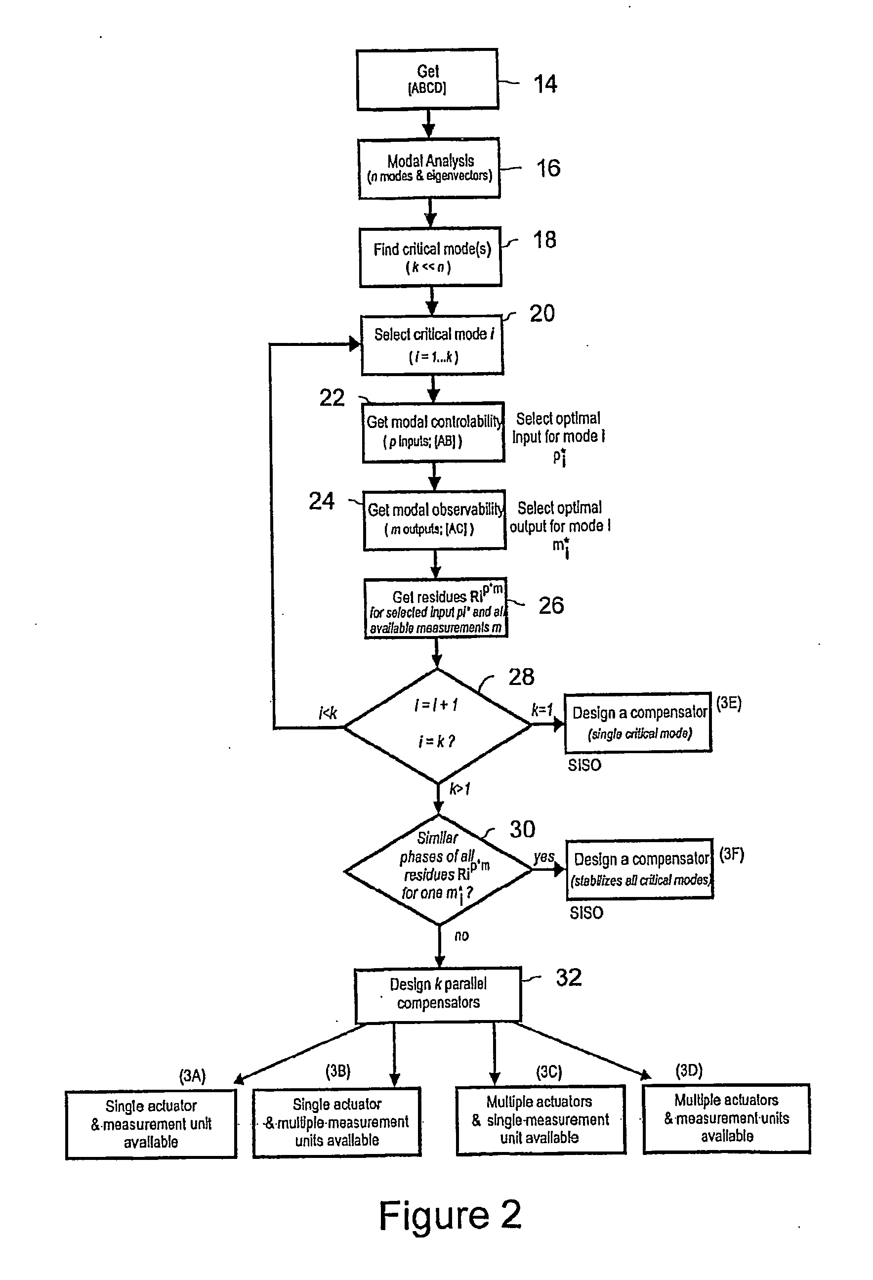
[0025]According to a first exemplary aspect of the present disclosure, a method is provided for damping multiple electromagnetic oscillations in a power system. The method can include, for example, obtaining phasor data signals from at least one power system location, extracting each oscillating mode from within the signal and analyzing each oscillating mode, and damping each oscillating mode based on the analysis and applying a control signal derived from the damped oscillating mode to a power flow control device in the power system. According to an exemplary embodiment, the step of extracting an oscillating mode can include selection and mode residue maximisation.

[0...


PUM


Abstract

Exemplary embodiments of the present disclosure provide a method and controller for damping multimode electromagnetic oscillations in electric power systems which interconnect a plurality of generators and consumers. The controller for damping such oscillations includes a phasor measurement unit (PMU) and a power oscillation damper (POD) controller. Each oscillating mode signal is damped and then superposed to derive a control signal. A feedback controller is used to feedback the control signal to a power flow control device in the power system.

Description

RELATED APPLICATIONS[0001]This application is a continuation application under 35 U.S.C. §120 of PCT / EP2008 / 053713, which was filed as an International Application on Mar. 28, 2008 designating the U.S., and which claims the benefit under 35 U.S.C. §119 of U.S. Provisional Patent No. 60 / 908,595 filed on Mar. 28, 2007. The entire contents of each prior application are hereby incorporated by reference in their entireties.FIELD[0002]The present disclosure relates to the field of damping multimode electromagnetic oscillations in electric power systems interconnecting a plurality of generators and consumers.BACKGROUND INFORMATION[0003]In the wake of the ongoing deregulations of the electric power markets, load transmission and wheeling of power from distant generators to local consumers has become common practice. As a consequence of the competition between utilities and the emerging need to optimize assets, increased amounts of electric power are transmitted through the existing networks...

Claims


Application Information

Patent Timeline
28 Jan 2010
Publication
US20100023179A1
IPC
G06F19/00
CPC
H02J3/24; Y04S10/265; Y02E60/728; Y02E60/00; Y04S10/00; Y04S10/22; Y02E40/70; H02J3/242
Inventors
KORBA, PETR; LARSSON, MATS