Rotor of drive motor of new energy automobile

A technology for new energy vehicles and driving motors, which is applied in electric components, electrical components, electromechanical devices, etc., can solve the problems of increasing the difficulty of calibrating dynamic balance, long glue filling process time, and increased rotor weight, etc., and it is easier to achieve the glue filling amount. Control, improve NVH performance, improve reliability effect

Pending Publication Date: 2017-05-10
芜湖杰诺瑞汽车电器系统有限公司
View PDF8 Cites 3 Cited by
  • Summary
  • Abstract
  • Description
  • Claims
  • Application Information

AI Technical Summary

Problems solved by technology

[0003] In the process of realizing the present invention, the inventor found that there are at least the following problems in the prior art: for the rotor in the prior art, due to the existence of flat keys or semicircular keys for appeal connection, key grooves need to be set on the rotor shaft, which weakens the shaft. Strength of
The multi-column arrangement of permanent magnets and permanent magnet slots according to the number of magnetic field poles leads to more glue filling times, long and complicated glue filling process, and the uneven glue filling in each row of permanent magnet slots affects the unbalance of the entire rotor, thereby increasing The next step is the difficulty of calibrating the dynamic balance, the weight of the rotor increases, and the power density decreases
[0006] In the prior art, the bearing pressure plate is pre-installed on the rotor shaft, and the bearing pressure plate and the rotor shaft are set to fit with a large gap. When the bearing pressure plate is fastened, it needs to be assisted to align the center of the rotor shaft, and the assembly efficiency is low.

Method used


Image

  • Rotor of drive motor of new energy automobile
  • Rotor of drive motor of new energy automobile
  • Rotor of drive motor of new energy automobile

Examples


Embodiment Construction

[0030] In order to make the object, technical solution and advantages of the present invention clearer, the implementation manner of the present invention will be further described in detail below in conjunction with the accompanying drawings.

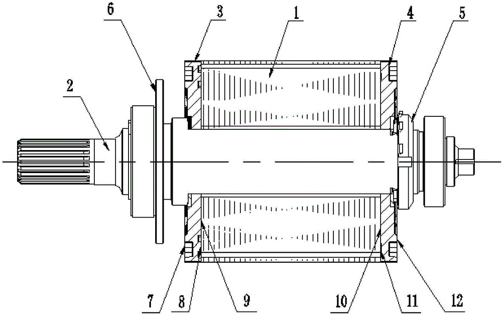
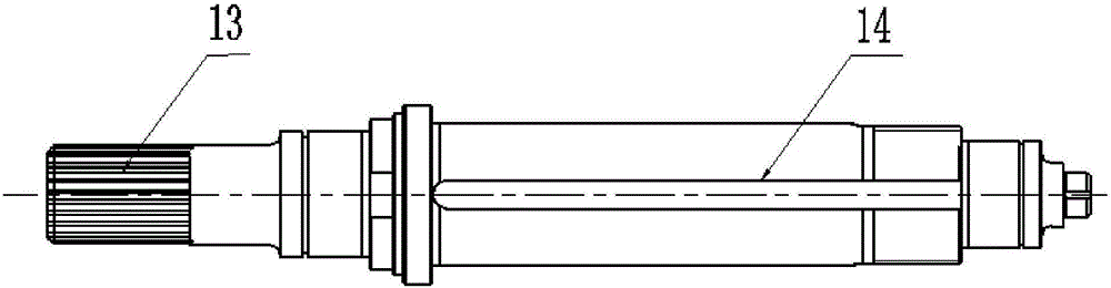
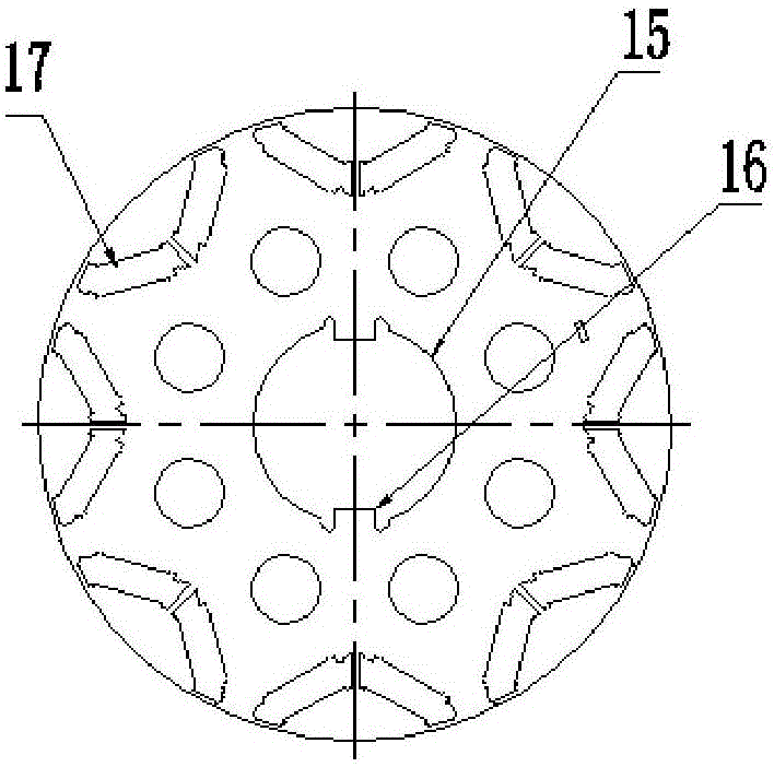
[0031] see Figure 1-9 , a new energy vehicle drive motor rotor, has:

[0032] The rotor core is provided with a permanent magnet slot extending from the upper end surface of the iron core to the lower end surface of the iron core. The middle part of the rotor iron core is provided with an axial inner circular hole of the rotor iron core. The inner wall of the inner circular hole of the rotor iron core is provided with There is a boss; the rotor shaft is provided with a plurality of keyway-shaped open slots in the rotor iron core matching section. The inner circular hole of the rotor iron core is provided with a plurality of flat key-shaped bosses. The rotor shaft is provided with a plurality of keyway-shaped open slots in the rotor ...


PUM


Abstract

The invention discloses a rotor of a drive motor of a new energy automobile. The rotor is provided with a rotor iron core, wherein the rotor iron core is provided with a permanent magnet groove extending from the upper end face of the lower end face of the iron core and, the middle part of the rotor iron core is provided with an axial iron core inner round hole and the inner wall of the inner round hole of the rotor iron core is provided with a boss; a rotor shaft fitting with the inner round hole of the rotor iron core and provided with an axial open groove fitting with the boss; an upper end board whose lower end face fits the upper end face of the iron core and is provided with a first guide groove communicating with a permanent magnet groove and also provided with an air inlet and air outlet both communicating with the first guide groove; a lower end board whose upper end face fits the lower end face of the iron core and provided with a second guide groove communicating with the permanent magnet groove. Therefore, rotor structural weight and rotation inertia are reduced; the manufacture cost is reduced; and the integral performance of the drive motor is improved.

Description

technical field [0001] The invention belongs to the technical field of drive motors for new energy vehicles, and in particular relates to a rotor for drive motors of new energy vehicles. Background technique [0002] The power transmission end of the drive motor rotor shaft is usually keyed. The rotor shaft is secured to the transmission by a keyed connection. [0003] In the process of realizing the present invention, the inventor found that there are at least the following problems in the prior art: for the rotor in the prior art, due to the existence of flat keys or semicircular keys for appeal connection, key grooves need to be set on the rotor shaft, which weakens the shaft. Strength of. At the same time, the existence of key connection gaps produces vibration and impact, which affects the stability and comfort of the motor's high-speed and variable load operation, thus failing to meet the NVH use requirements of automotive motors. In the prior art, the motor rotor i...

Claims


Application Information

Patent Timeline
Patent Type & Authority Applications(China)
IPC IPC(8): H02K1/27H02K5/20H02K5/24
CPCH02K1/27H02K5/20H02K5/24
Inventor 汪自稳
Owner 芜湖杰诺瑞汽车电器系统有限公司
Why Eureka
Try Eureka