Condensation pump assembly

A condensate pump and assembly technology, applied in the field of condensate pump control system, can solve problems such as stuck, burned micro switch, easy to generate large current, etc., and achieve the effect of controlling the movement of the floating ball, loose requirements, and convenient operation

Active Publication Date: 2017-05-24
浙江益而益智能科技有限公司
View PDF6 Cites 1 Cited by
  • Summary
  • Abstract
  • Description
  • Claims
  • Application Information

AI Technical Summary

Problems solved by technology

[0005] The purpose of the present invention is to provide a safe and reliable condensate pump control device. The technical problem to be solved is to overcome the phenomenon that multiple floating balls in the traditional condensate pump float up and down successively triggering multiple micro switches that are prone to jamming, and , in the traditional condensate pump, when the floating ball directly touches the micro switch on the plane, especially when the switch is in a critical position, the frequent action of the micro switch is likely to generate a large current, thus burning the micro switch

Method used


Image

  • Condensation pump assembly
  • Condensation pump assembly
  • Condensation pump assembly

Examples


Embodiment Construction

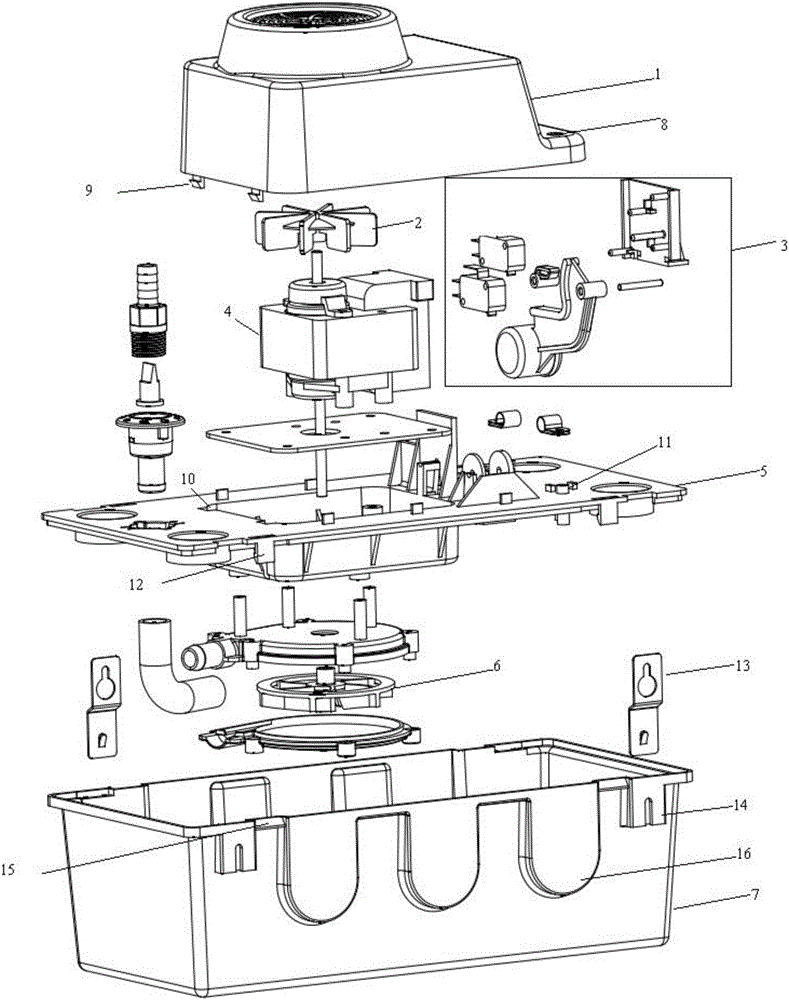
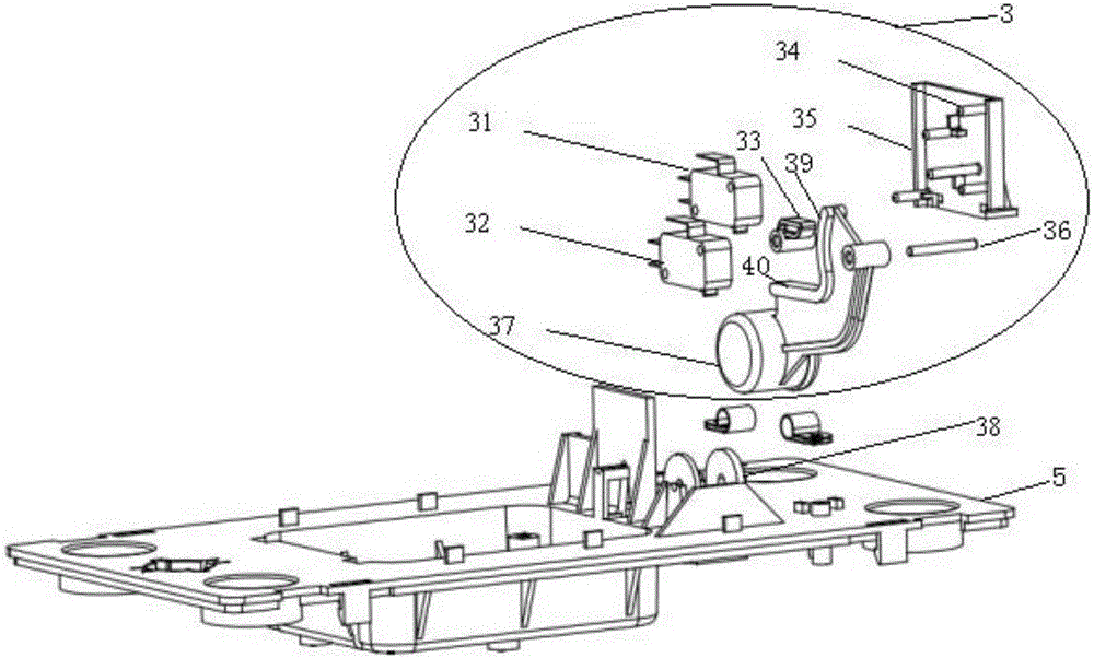
[0048] Through extensive and in-depth research, the inventor accidentally invented a new type of condensate pump assembly for the first time. The control system of single float and toggle button designed by anti-self-locking principle can ensure smooth triggering of two micro switches . The present invention has been accomplished on this basis.

[0049] Unless defined otherwise, all technical and scientific terms used herein have the same meaning as commonly understood by one of ordinary skill in the art to which this invention belongs.

[0050] In the description of the present invention, in order to clearly demonstrate the structure and working method of the present invention, many directional words will be used for description, but "front", "rear", "left", "right", "outer" should be used , "inward", "inward", "outward" and other words are understood as convenient terms, and should not be understood as limiting words, which are only for the convenience of describing the pre...


PUM


Abstract

The invention provides a condensation pump assembly, and in particular, relates to a condensation pump control system. The control system comprises a first floating ball, a first micro switch, a second micro switch, a dial button and a fixed frame; the first micro switch, the second micro switch and the dial button are fixed on the fixed frame through pins; and the first floating ball is provided with a trigger surface in the horizontal direction, and an arc contact surface concentric with a rotating hole of the first floating ball.

Description

technical field [0001] The invention belongs to the field of air-conditioning equipment, and in particular relates to a condensate pump assembly, and more specifically to a condensate pump control system. Background technique [0002] The working principle of the existing condensate pump is as follows: the impeller of the water pump is driven by an air-cooled motor, the impeller rotates at a high speed and generates a negative pressure in the center of the impeller, and the water outside the pump body of the water pump is sucked into the water pump, and the impeller converts mechanical energy into fluid kinetic energy, Fluid exits the outlet of the pump. [0003] At present, the water pump is usually automatically controlled by using two or more control floats in the water storage tank, and each float moves up and down to trigger different micro switches. Because the number of floating balls is usually large and the structure is complex, the requirements for the guidance of...

Claims


Application Information

Patent Timeline
Patent Type & Authority Applications(China)
IPC IPC(8): F04D15/02F04D15/00
CPCF04D15/00F04D15/0218
Inventor 汪声艳
Owner 浙江益而益智能科技有限公司
Why Eureka
Try Eureka