Intelligent sweeper

A sweeping machine, intelligent technology, applied to manual sweeping machinery, cleaning carpets, cleaning floors, etc., can solve the problems of unable to automatically clean the filter tube, reduce the service life of the sweeper, loose parts, etc., to avoid secondary dust, Reasonable structure and prolonging service life

Inactive Publication Date: 2017-05-31
泉州市力丰机电科技有限公司
View PDF13 Cites 1 Cited by
  • Summary
  • Abstract
  • Description
  • Claims
  • Application Information

AI Technical Summary

Problems solved by technology

However, it cannot automatically clean the filter tube, and the use of a vacuum pump will absorb larger dust particles on the filter tube to block the filter tube, so it is necessary to disassemble the dust collection tank and manually clean the filter tube, which is inconvenient to use
Also Chinese Patent No.: 201520462681.3 discloses a sweeping machine, the structure of which includes a frame, and a moving wheel, a brush plate, a rolling brush, a dustbin, a dust isolation device, and a suction motor installed on the frame; The box, the dust isolation device, and the frame form a space with open ends. The entrance of the garbage bin is one of the open ends, and the intake of the dust isolation device is the other open end; when the sweeper is working, the rotating brush disc The rubbish is moved into the path of the roller brush, and the rotating roller brush moves the rubbish directly into the dustbin, and the air in the dustbin is filtered by the dust isolation device and then sucked out of the body by the suction motor; but the dust isolation device The dust filter uses a vibrating motor to vibrate to clean up the clogged dust on the dust filter. This method makes the whole machine affected by the vibration transmission of the vibrating motor, and it is easy to cause the parts of the sweeper to loosen due to vibration. The damage of the sweeper reduces the service life of the sweeper

Method used


Image

  • Intelligent sweeper
  • Intelligent sweeper

Examples


Embodiment Construction

[0017] The present invention will be further described in conjunction with the accompanying drawings and specific embodiments.

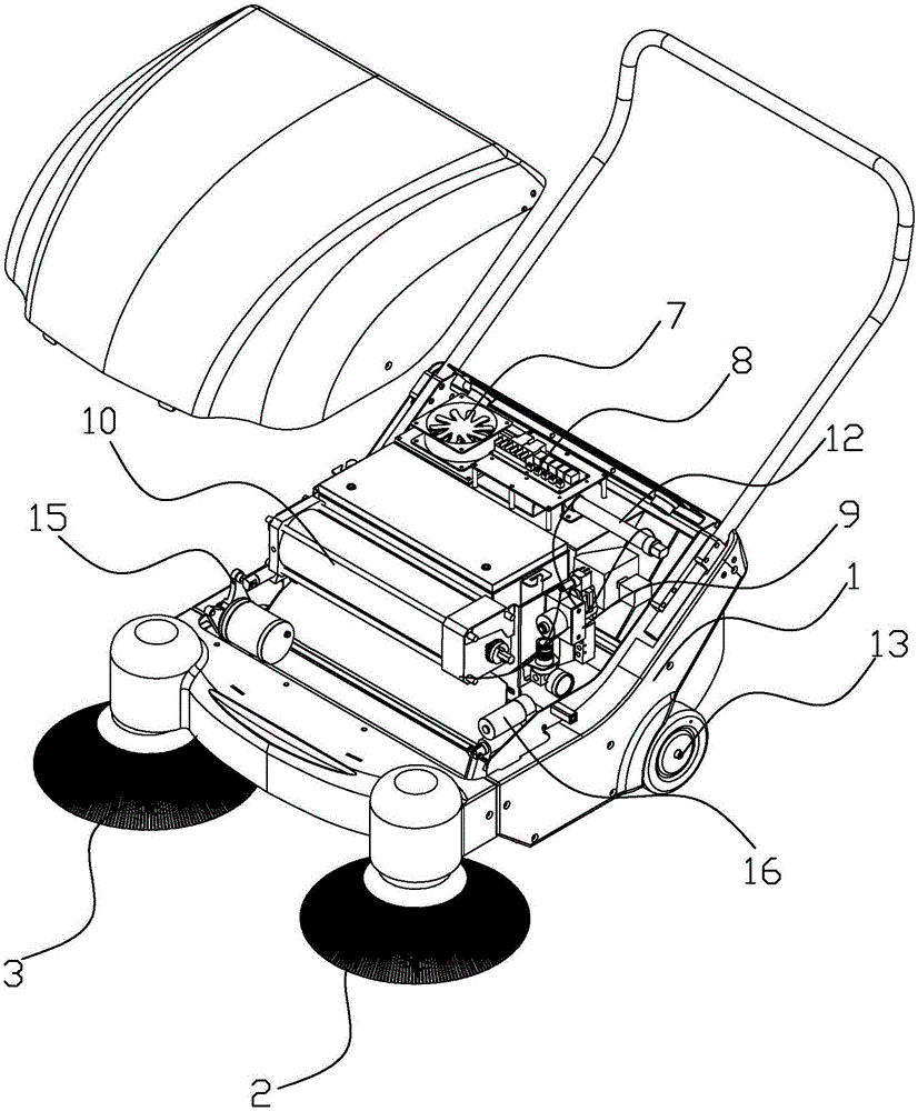
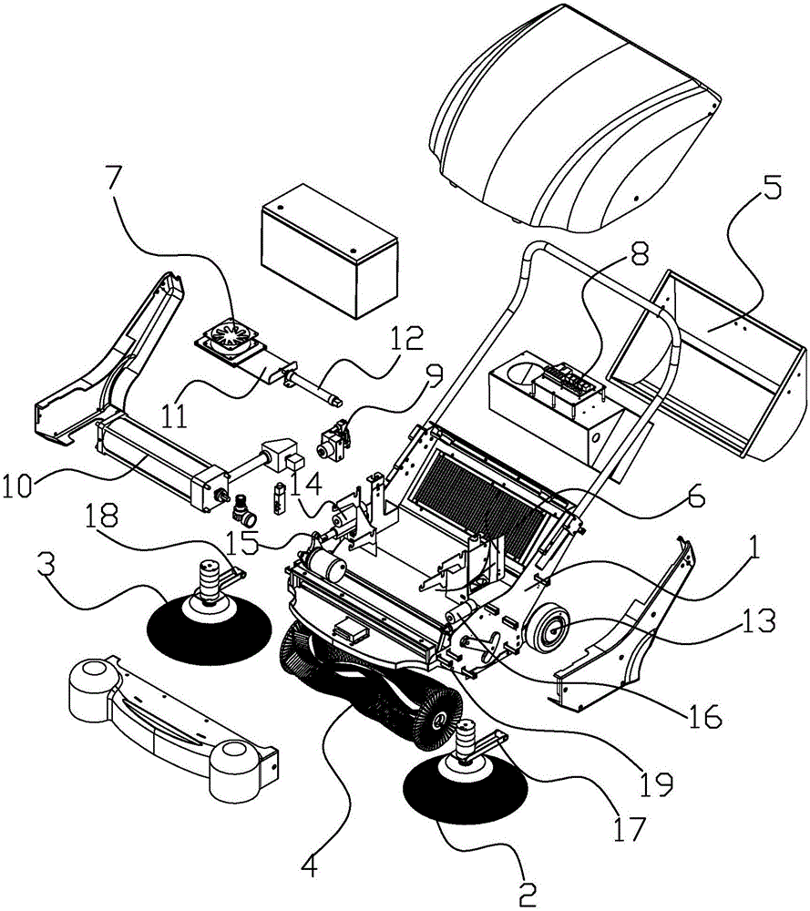
[0018] refer to Figure 1-Figure 2, the preferred intelligent sweeper of the present invention includes a frame 1, a first brush plate 2, a second brush plate 3, a rolling brush 4, a dust box 5, a dust filter 6, a suction motor 7, a controller 8, Delay control circuit, air compressor 9, multiple solenoid valves, air storage tank 10, sealing plate 11, pushing mechanism 12, barometer, control panel and displacement sensor; Moving roller 13, the second lifting mechanism includes a second drive unit 16, a second swing arm 17, a third swing arm 18 and a support shaft 19, one end of the second swing arm 17 is fixed to the first brush plate 2 Then, one end of the third swing arm 18 is fixedly connected to the second brush plate 3, and the other end of the second swing arm 17 and the other end of the third swing arm 18 are respectively fixedly connected to ...


PUM


Abstract

The invention relates to the technical field of cleaning machines and provides an intelligent sweeper. The intelligent sweeper comprises a rack, a first brush plate, a rolling brush, a dust collection box, a dust filtering screen, an air suction motor, a controller, an air compressor, a plurality of electromagnetic valves, an air storage tank, a sealing plate and a pushing mechanism. The sealing plate is arranged on an exhaust duct, between the dust filtering screen and the air suction motor, on the rack in a sliding mode, the pushing mechanism is connected to the sealing plate and drives the sealing plate to seal / open the exhaust duct between the dust filtering screen and the air suction motor, the air storage tank and the air compressor are arranged on the rack, an air outlet of the air compressor is communicated with an air inlet of the air storage tank through the electromagnetic valve, an air outlet of the air storage tank is communicated with a space formed by the dust filtering screen, the dust collection box and the rack through the electromagnetic valves, and the air suction motor, the air compressor and the electromagnetic valves are connected with the controller and controlled by the controller. By means of the intelligent sweeper, the problems that in an existing sweeper, a dust filtering screen is inconvenient to clean, and a sweeper base is affected by vibration of a vibrating motor and accordingly damaged are solved.

Description

technical field [0001] The invention relates to the technical field of cleaning machines, in particular to an intelligent sweeping machine. Background technique [0002] With the improvement of people's living standards, people's requirements for environmental sanitation are getting higher and higher. At present, the cleaning of environmental sanitation and the cleaning of small areas mainly rely on manual cleaning. The current sweeping method is very unscientific. Reconsider the way the cleaners sweep the floor. Through observation, it is found that a large amount of dust is caused by the waving of the broom. The broom is the source of dust. Physical strength, the cleaning speed is not only slow but also very inefficient. Therefore, the broom must be redesigned so that it will not stir up a lot of dust during use, to ensure the health of the cleaning workers, and at the same time to further improve the cleaning efficiency. For this reason, the floor sweeper came out at the...

Claims


Application Information

Patent Timeline
IPC IPC(8): A47L11/24A47L11/40
CPCA47L11/24A47L11/40A47L11/4002A47L11/4011A47L11/4033A47L11/4038A47L11/4041A47L11/4058
Inventor 黄伍桂严俊锋
Owner 泉州市力丰机电科技有限公司
Why Eureka
Try Eureka