A hollow shaft fixture

A tooling fixture and hollow shaft technology, which is applied in the field of hollow shaft tooling fixtures, can solve the problems that hollow shafts cannot be processed, and achieve high practicability, high clamping effect and switch control effect

Active Publication Date: 2019-06-18
重庆市永川区中川科技发展有限责任公司
View PDF4 Cites 0 Cited by
  • Summary
  • Abstract
  • Description
  • Claims
  • Application Information

AI Technical Summary

Problems solved by technology

[0003] The invention provides a hollow shaft tooling fixture to solve the problems in the prior art that the clamp needs to be manually opened and clamped, and the clamped part of the hollow shaft cannot be processed by clamping the hollow shaft on both sides or outside.

Method used


Image

  • A hollow shaft fixture
  • A hollow shaft fixture
  • A hollow shaft fixture

Examples


Embodiment Construction

[0023] In order to enable those skilled in the art to better understand the technical solutions in the embodiments of the present invention, and to make the above-mentioned purposes, features and advantages of the embodiments of the present invention more obvious and understandable, the following describes the technical solutions in the embodiments of the present invention in conjunction with the accompanying drawings For further detailed explanation.

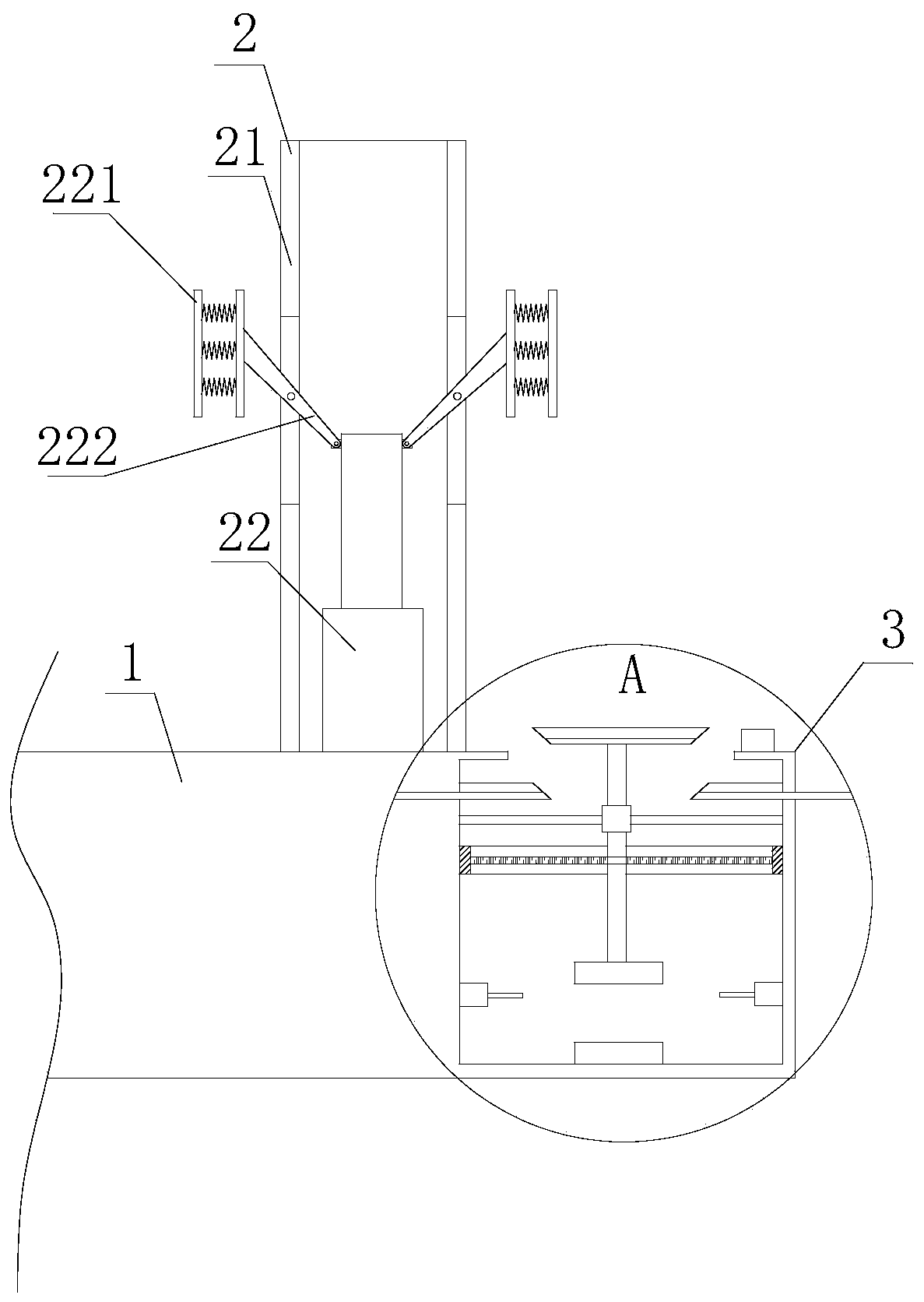
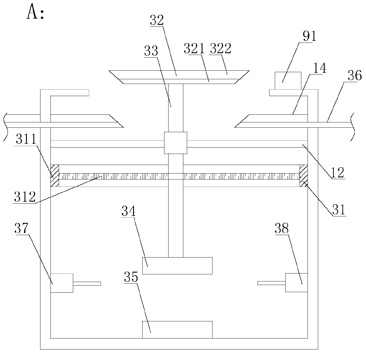
[0024] As shown in the figure, a hollow shaft tooling fixture includes a base 1, the center of the base is provided with an inner clamp arm 2 for passing through the interior of the hollow shaft, an automatic switch device 3 is provided on the base, and the automatic switch is connected to the axial direction of the side wall of the hollow shaft. One end cooperates with the switch, and the inner clamping arm is provided with an electric push rod 22 and a fixed cylinder 21, the fixed cylinder is an inner hollow structure, the ele...


PUM


Abstract

The invention provides a hollow shaft tool fixture. The hollow shaft tool fixture comprises a base; an inner clamping arm for passing through the interior of a hollow shaft is arranged in the center of the base; the base is provided with an automatic switch device; the automatic switch and one axial end of the side wall of the hollow shaft are matched for opening and closing; the inner clamping arm is provided with a linear actuator and a fixed cylinder; the fixed cylinder is of a hollow structure; the linear actuator is positioned in the fixed cylinder; a body of the linear actuator is hinged to one ends of multiple clamping arms; the middle parts of the clamping arms are also hinged to the side wall of the fixed cylinder; through grooves are longitudinally formed in the parts, hinged with the clamping arms, of the fixed cylinder; and fixing pieces are arranged at the other ends of the clamping arms, and include fixing blocks and springs. The hollow shaft tool fixture is used for solving such problems as need of manually starting the clamping action and incapability of machining the clamped part of the hollow shaft due to clamping of the hollow shaft from two sides or the outer side in the prior art.

Description

technical field [0001] The invention relates to the field of mechanical processing, in particular to a hollow shaft fixture. Background technique [0002] With the development of the machinery industry, the requirements for the shape of the parts vary widely. Different shapes of workpieces must adopt different forms of clamping methods when processing on the machine tool. For example, when processing the length of the hollow shaft and grinding its edge, the hollow shaft needs to be Fixing, the traditional fixing method uses a clamping and a top method to clamp and fix the side wall of the hollow shaft at the same time. When grinding the outside of the side wall of the hollow shaft, because part of the side wall is blocked by the clamping arm, it cannot be done. Grinding requires manual secondary processing to complete; in addition, when the hollow shaft is fixedly installed, it is necessary to place the hollow shaft on the fixture first, turn on the electric switch, and then...

Claims


Application Information

Patent Timeline
Patent Type & Authority Patents(China)
IPC IPC(8): B23Q3/08B24B41/06
CPCB23Q3/08B24B41/06
Inventor 魏星
Owner 重庆市永川区中川科技发展有限责任公司
Why Eureka
Try Eureka