Protection device for hoisting wire rope of magnetic conveyor

A protection device and steel wire rope technology, which is applied in the direction of hoisting device and spring mechanism, etc., can solve the problems of high production cost and complex structure

Active Publication Date: 2019-11-08
MCC BAOSTEEL TECH SERVICE
View PDF12 Cites 0 Cited by
  • Summary
  • Abstract
  • Description
  • Claims
  • Application Information

AI Technical Summary

Problems solved by technology

Although the wire rope de-grooving protection device can prevent the wire rope from de-grooving, the structure is complex and the manufacturing cost is high

Method used


Image

  • Protection device for hoisting wire rope of magnetic conveyor
  • Protection device for hoisting wire rope of magnetic conveyor
  • Protection device for hoisting wire rope of magnetic conveyor

Examples


Embodiment Construction

[0038] The implementation of the present invention will be illustrated by specific specific examples below, and those skilled in the art can easily understand other advantages and effects of the present invention from the contents disclosed in this specification.

[0039] It should be noted that the structures, proportions, sizes, etc. shown in the drawings attached to this specification are only used to match the content disclosed in the specification, for those who are familiar with this technology to understand and read, and are not used to limit the implementation of the present invention. Limiting conditions, so there is no technical substantive meaning, any modification of structure, change of proportional relationship or adjustment of size, without affecting the effect and purpose of the present invention, should still fall within the scope of the present invention. The disclosed technical content must be within the scope covered. At the same time, terms such as "upper"...


PUM


Abstract

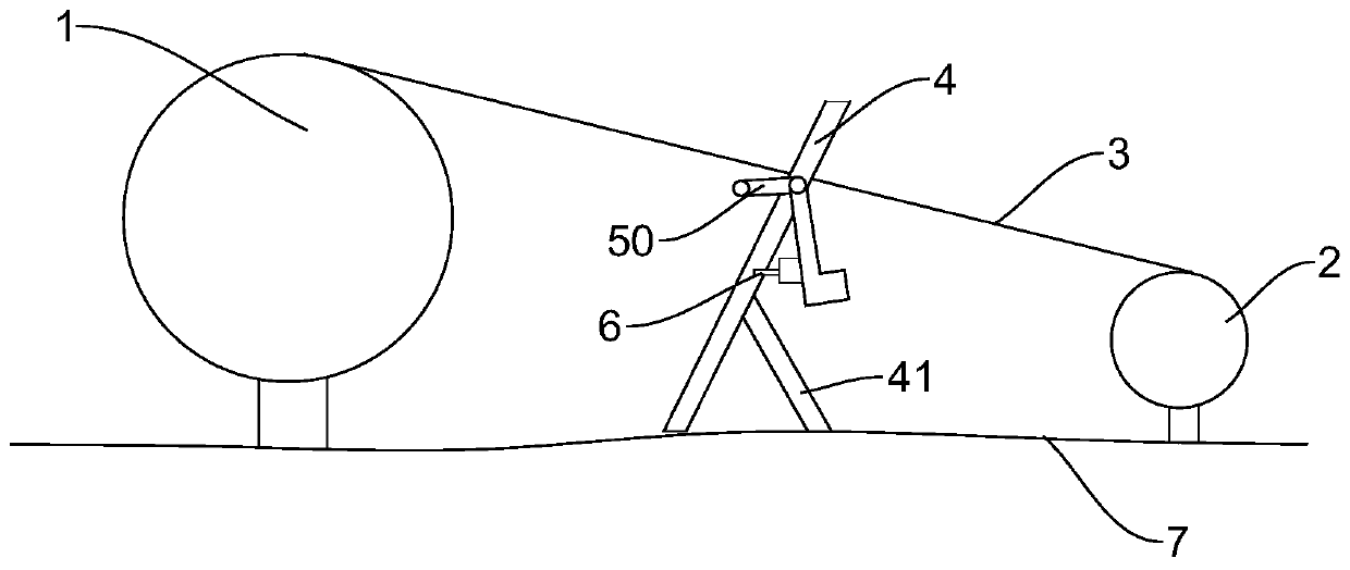
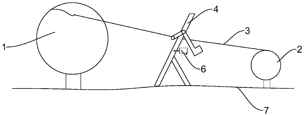
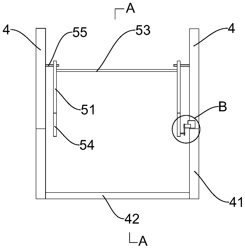
The invention provides a slot disengagement protection device for a hoist wire rope pf a magnetic conveyor. The slot disengagement protection device comprises two main fulcrum bars positioned between a reel and a fixed pulley, wherein the two main fulcrum bars are erected on the ground; a link mechanism is arranged between the two main fulcrum bars and comprises two balance bars; each balance bar is hinged to the corresponding main fulcrum bar and comprises a first subsidiary bar and a second subsidiary bar which intersect to form an angle; the two second subsidiary bars are connected through a cross bar; the weights of the first subsidiary bars are larger than those of the second subsidiary bars; the cross bar is positioned under a wire rope; and a travel switch is arranged on each main fulcrum bar, and when the first subsidiary bars are in contact with the corresponding travel switches, the control loop of the reel is in an on state. As the balance bars are arranged, the travel switches are in the normally closed state, and the main control loop is kept connected; and when the wire rope is disengaged from a slot and presses the cross bar, the travel switches are turned off, the main control loop is disconnected, and equipment can stop immediately, and repair personnel can quickly handle the situation for reuse.

Description

technical field [0001] The invention relates to the field of magnetic conveyors, in particular to a protective device for hoisting wire ropes of magnetic conveyors. Background technique [0002] The magnetic conveyor, also known as the stacker, is a lifting device for the upper and lower roller tables of steel plates. Its overall structure and working principle are similar to those of bridge cranes, but the span and lifting height are different, and there is no trolley traverse mechanism. In the production process, due to improper operation and other reasons, the wire rope of the hoisting mechanism often escapes from the drum or the fixed pulley. Most of the time, the operator cannot find out in time and continue to operate, thus directly causing the wire rope of the drum to fall out of the groove and damage the bearing seat. , wire rope breakage, fixed pulley flanging and other equipment accidents. After the wire rope de-grooving equipment accident occurs, the maintenance ...

Claims


Application Information

Patent Timeline
Patent Type & Authority Patents(China)
IPC IPC(8): B66D1/54
CPCB66D1/54
Inventor 杜国强耿国栋朱金才
Owner MCC BAOSTEEL TECH SERVICE
Why Eureka
Try Eureka