Knee joint structure used for lower limb exoskeleton robot

An exoskeleton robot and knee joint technology, applied in the field of robotics, can solve problems such as the bulky structure of the thigh drive sprocket, the inability to adjust the instantaneous center of rotation, and the inability of users to provide assistance for sitting and standing.

Active Publication Date: 2017-06-27
上海理工资产经营有限公司
View PDF9 Cites 21 Cited by
  • Summary
  • Abstract
  • Description
  • Claims
  • Application Information

AI Technical Summary

Problems solved by technology

Most of the current research on lower extremity exoskeletons focuses on the active drive of motors in each joint, but the size, weight, and continuous use time of the motors greatly limit the development of lower extremity exoskeletons.
[0003] Application number 201610948436.2 proposes a lower extremity exoskeleton power-assisted structure, which is driven by hydraulic pumps at the hip joint, knee joint, and ankle joint. Although it can achieve more driving degrees of freedom, the weight and operation of the entire lower extremity exoskeleton are difficult. greatly increased
[0004] Application number 201410735565.4 proposes a lower extremity exoskeleton robot structure for assisting walking. Drives are installed at the hip joint and knee joint, and the knee joint is assisted by a motor. This knee joint structure cannot adjust the instantaneous center of rotation when the human body walks. And increase the overall weight of the exoskeleton and power consumption
[0005] Application number 201410353073.9 proposes a single-drive linkage type lower limb power-assisted exoskeleton structure. Although it is also controlled by a single motor, the thigh drive sprocket structure of the waist module is bulky and too large, and it cannot provide users with sitting and standing functions. help
[0006] When the human body walks normally, the rotation center of the knee joint changes dynamically. The current motor-driven and hydraulically driven lower extremity exoskeleton knee joints cannot simulate such changes in the knee joint; while the human body posture (sitting-standing, standing- Sit down) transformation is realized through the driving structure, which increases the power consumption of the motor and complicates the driving structure

Method used


Image

  • Knee joint structure used for lower limb exoskeleton robot
  • Knee joint structure used for lower limb exoskeleton robot
  • Knee joint structure used for lower limb exoskeleton robot

Examples


Embodiment Construction

[0021] The present invention will be described in detail below in conjunction with the accompanying drawings.

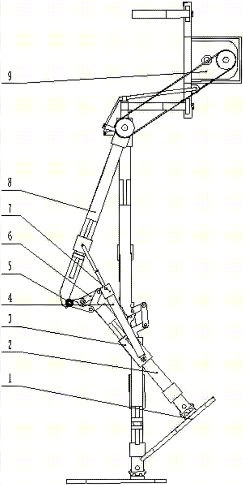
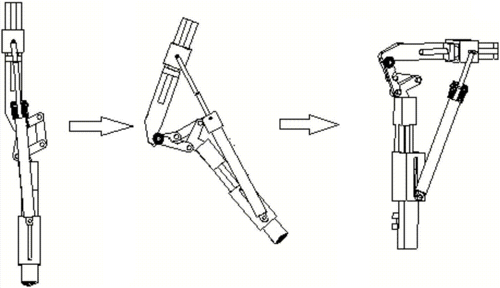
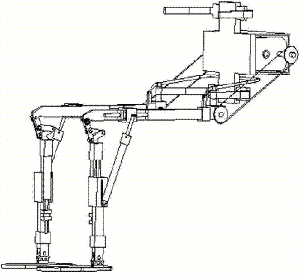
[0022] Such as Figure 1 to Figure 4 As shown, the present invention provides a knee joint structure for a lower extremity exoskeleton robot, including a foot plate 1, a lower leg assembly 2, a gas spring chute mechanism 3, a gas spring 4, a booster leaf spring 5, a four-link knee joint 6, Gas spring locking mechanism 7, thigh assembly 8, hip joint driving motor 9.

[0023] The shank assembly 2 and the thigh assembly 8 are connected by a four-bar knee joint 6, and a gas spring 4 is also installed between the shank assembly 2 and the thigh assembly 8. One end of the gas spring 4 is connected to the thigh assembly 8, and the other end is connected to the thigh assembly 8. The gas spring chute mechanism 3 fixed on the calf assembly 2 is slidably connected, and the gas spring 4 is used to realize power assisting when standing up to sitting down, and sitting down to stan...


PUM


Abstract

The invention relates to a knee joint structure used for a lower limb exoskeleton robot. A shank assembly is connected with a thigh assembly through a four-bar linkage knee joint, and a gas spring is further mounted between the shank assembly and the thigh assembly. One end of the gas spring is connected to the thigh assembly, and the other end of the gas spring is in sliding connection with a gas spring sliding groove mechanism fixed to the shank assembly. By utilizing the gas spring to provide assistance, conversion from standing to sitting and conversion from sitting to standing are realized. When a user normally walks, the slip of the gas spring, caused by the bending of the knee joint, cannot reach the bottom of the gas spring sliding groove mechanism, so that the gas spring is not compressed or stressed, and normal walking is not affected. When the user wants to convert from standing to sitting or convert from sitting to standing, the slip of the gas spring, caused by the bending of the knee joint, can reach the bottom of the gas spring sliding groove mechanism, the gas spring is compressed and stressed, and energy is stored, so that assistance is provided for converting from standing to sitting and converting from sitting to standing.

Description

technical field [0001] The present invention relates to a knee joint structure for a lower extremity exoskeleton robot, in particular to a knee joint non-driven knee joint structure that is used to transform from standing to sitting, and from sitting to standing to provide assistance without affecting the normal gait. A booster structure belongs to the technical field of robots. Background technique [0002] An exoskeleton is a robot that combines artificial intelligence and mechanical power devices; it is worn outside the operator and integrates technologies such as control, sensing and man-machine integration to provide support, movement, protection and other functions. It is used in military, It has broad application prospects in life, medical treatment and other aspects. The human lower extremity exoskeleton robot is a human-machine integrated mechanical device that can be worn by humans, which can provide an external structure for configuring, building and protecting t...

Claims


Application Information

Patent Timeline
Patent Type & Authority Applications(China)
IPC IPC(8): B25J17/02B25J9/00
CPCB25J9/0006B25J17/0258
Inventor 曹武警魏小东余灵谢巧莲喻洪流胡冰山孟青云
Owner 上海理工资产经营有限公司
Why Eureka
Try Eureka