
A method and device for determining image processing threshold

An image processing and threshold technology, applied in the field of image processing, can solve problems such as temperature rise, large difference in image brightness, and influence of image data collection, so as to reduce brightness difference and realize reasonable call effect

Active Publication Date: 2019-12-06
SHENZHEN YIHUA COMP +2
View PDF6 Cites 0 Cited by
  • Summary
  • Abstract
  • Description
  • Claims
  • Application Information

AI Technical Summary

Problems solved by technology

[0002] Currently, image sensors are used to collect image data of banknotes in the process of detecting banknotes in bank financial transaction equipment. However, the sensors work in different environments, and the brightness of the collected images varies greatly.
Specifically, whether it is the change of the ambient temperature or the temperature rise caused by the heat generated by the sensor, it has a great impact on the image data collection of banknotes.

Method used


Image

  • A method and device for determining image processing threshold
  • A method and device for determining image processing threshold

Examples


Embodiment 1

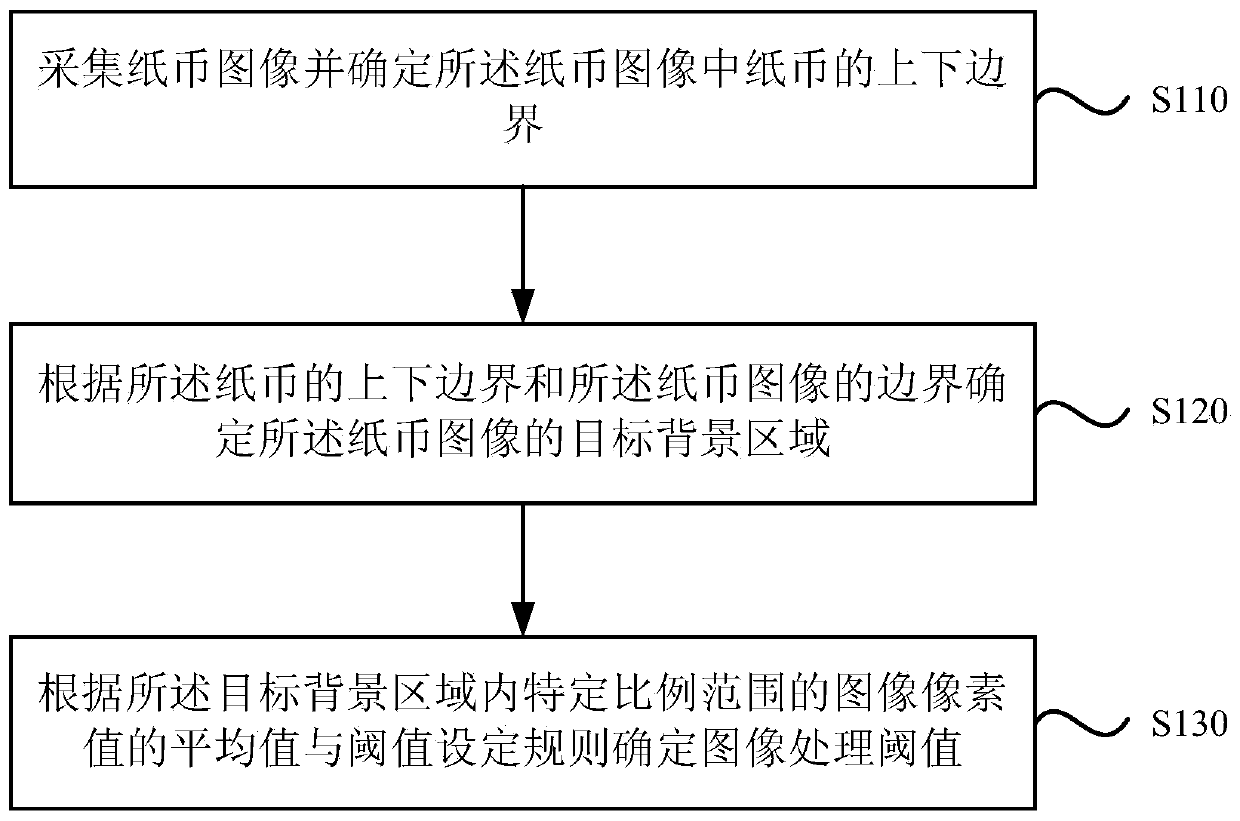
[0048] Please refer to the attached figure 1 , is a schematic flow chart of a method for determining an image processing threshold in Embodiment 1 of the present invention. This method is suitable for processing banknotes such as using algorithms related to image pixel values ​​and thresholds, and sensors are used to collect image data of banknotes, and In the scene where the image processing threshold needs to be determined, the method is executed by the device for determining the image processing threshold, which can be realized by software and / or hardware, and can be integrated into an image processor or a financial transaction device. The method specifically includes the following steps:

[0049] S110. Collect the banknote image and determine the upper and lower boundaries of the banknote in the banknote image.

[0050] It should be noted that the method of determining the upper and lower boundaries of the banknote in the image through the banknote image collected by the ...

Embodiment 2

[0066] Please refer to the attached figure 2 , is a schematic structural diagram of a device for determining an image processing threshold provided in Embodiment 2 of the present invention, and the device specifically includes the following modules:

[0067] The upper and lower boundary determination module 21 is used to collect the banknote image and determine the upper and lower boundaries of the banknote in the banknote image;

[0068] A target area determining module 22, configured to determine the target background area of ​​the banknote image according to the upper and lower boundaries of the banknote and the boundary of the banknote image;

[0069] The threshold determination module 23 is configured to determine the image processing threshold according to the average value of image pixel values ​​in a specific proportion range in the target background area and threshold setting rules.

[0070] Preferably, the target area determination module includes:

[0071] A firs...


PUM


Abstract

The embodiment of the present invention discloses a method and device for determining an image processing threshold. The method includes: collecting a banknote image and determining the upper and lower boundaries of the banknote in the banknote image; Determining the target background area of ​​the banknote image; determining the image processing threshold according to the average value of image pixel values ​​in a specific proportion range in the target background area and threshold setting rules. Based on the above method and device, by collecting the image of the background area and calculating the average value of the pixel values ​​of the image within a specific proportion of the area, compared with the threshold setting rules, the rational call of the image processing threshold can be realized, which can ensure that the sensor can be used according to different The working environment invokes image processing thresholds to minimize brightness differences in captured images.

Description

technical field [0001] Embodiments of the present invention relate to the technical field of image processing, and in particular to a method and device for determining an image processing threshold. Background technique [0002] Currently, image sensors are used to collect image data of banknotes in the process of detecting banknotes by bank financial transaction equipment. However, the sensors work in different environments, and the brightness of the collected images varies greatly. Specifically, whether it is the change of the ambient temperature or the temperature rise caused by the heat generated by the sensor, it has a great impact on the image data collection of the banknote. For example, the overall brightness of banknote image data collected by the sensor in a high-temperature environment will be stronger than that of banknote image data collected in a normal temperature environment. The processing methods are different, and how to adjust the processing method of th...

Claims


Application Information

Patent Timeline
Patent Type & Authority Patents(China)
IPC IPC(8): G07D7/20G06K9/20G06T7/11G06T7/136
CPCG07D7/2008G06V10/10
Inventor 李杰
Owner SHENZHEN YIHUA COMP
Learn More