Fluid sampling member for closed body fluid storage device

A body fluid and ring-shaped technology, applied in the field of medical devices, can solve the problems of high cost, complex production and processing, and insufficient speed of diversion, and achieve the effects of reducing preparation costs, shortening processing time, and reducing dosage

Inactive Publication Date: 2017-07-04
WUXI KAISHUN MEDICAL DEVICE MFG CO LTD
View PDF3 Cites 2 Cited by
  • Summary
  • Abstract
  • Description
  • Claims
  • Application Information

AI Technical Summary

Problems solved by technology

Even if the liquid taking part is equipped with an exhaust channel, during the liquid guiding process, the liquid will still flow to the exhaust port to block the exhaust port, resulting in liquid retention
In addition, the liquid extraction part is equipped with an exhaust channel, but the production and processing are more complicated, the cost is high, the production efficiency is low, and the speed of diversion is not fast enough

Method used


Image

  • Fluid sampling member for closed body fluid storage device
  • Fluid sampling member for closed body fluid storage device
  • Fluid sampling member for closed body fluid storage device

Examples


Embodiment 1

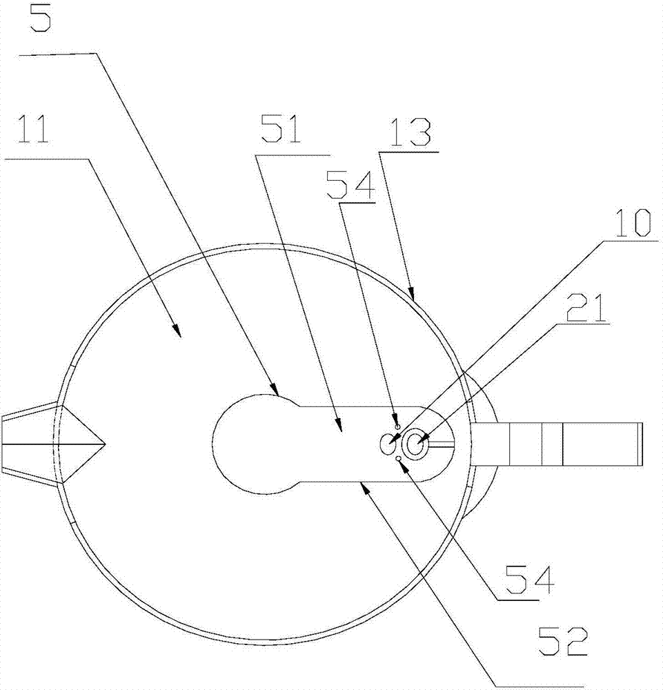
[0062] Example 1: The following is attached figure 1 Attached Figure 5 , Picture 11 To further explain the present invention:

[0063] A liquid taking part for a closed body fluid indwelling device, comprising a ring-shaped side wall A 1 and a ring-shaped side wall B 2.

[0064] The annular side wall armor 1 has an upper opening 11 and a lower opening 12. The annular side wall armour 1 includes an annular side wall armour upper part 1a, a bottom sealing plate 5 and an annular side wall armour lower part 1b. The annular side wall armour 1 encloses and forms a diversion channel 10. The liquid guiding channel 10 has a liquid inlet 19a and a liquid outlet 19b. The upper part 1a of the annular side wall is used for collecting liquid, the lower part 1b of the annular side wall is used to connect with the test tube, and the bottom sealing plate 5 is respectively connected with the upper part 1a of the annular side wall and the lower part 1b of the annular side wall. The lower part 1b...

Embodiment 2

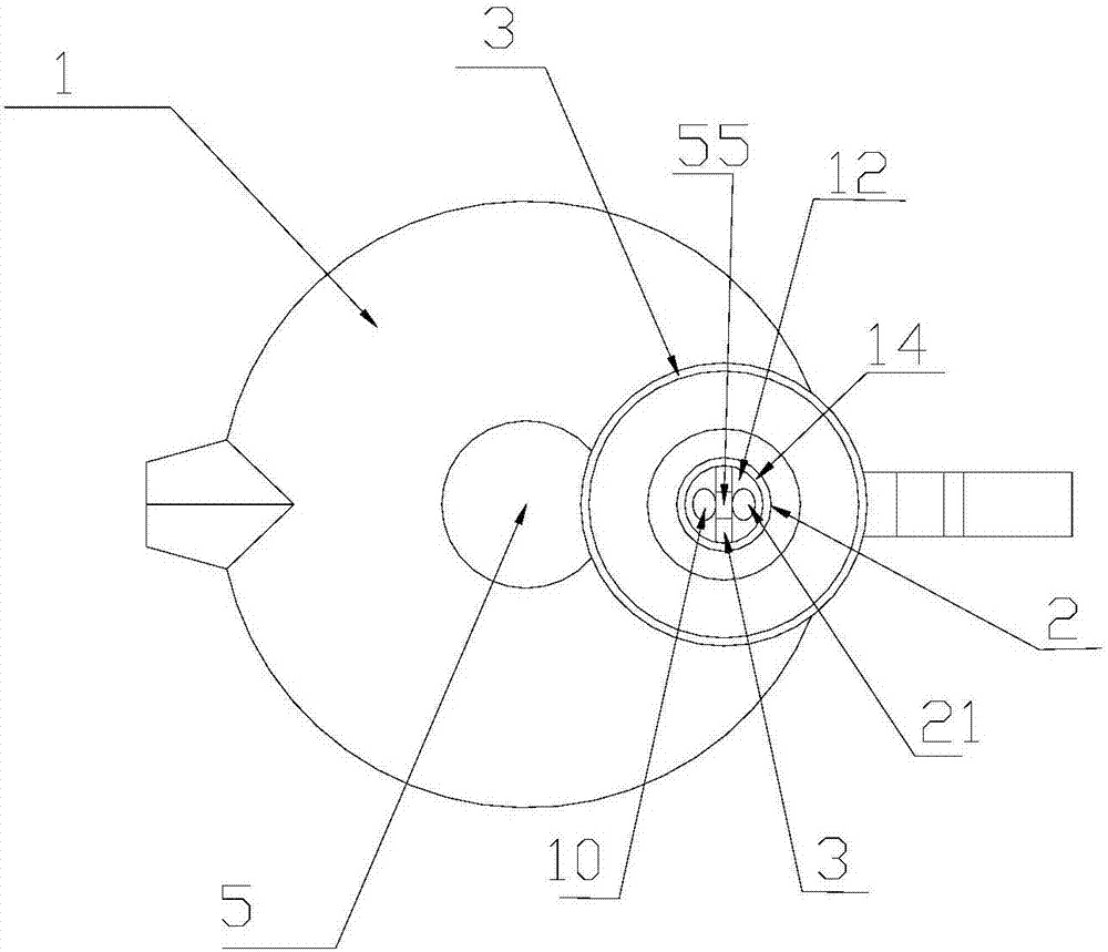
[0085] Embodiment 2: The following is attached Image 6 Attached Picture 10 , Picture 12 To further explain the present invention:

[0086] A liquid taking part for a closed body fluid indwelling device, comprising a ring-shaped side wall A 1 and a ring-shaped side wall B 2.

[0087] The annular side wall armor 1 has an upper opening 11 and a lower opening 12. The annular side wall armour 1 includes an annular side wall armour upper part 1a, a bottom sealing plate 5 and an annular side wall armour lower part 1b. The annular side wall armour 1 encloses and forms a diversion channel 10. The liquid guiding channel 10 has a liquid inlet 19a and a liquid outlet 19b. The upper part 1a of the annular side wall is used for collecting liquid, the lower part 1b of the annular side wall is used to connect with the test tube, and the bottom sealing plate 5 is respectively connected with the upper part 1a of the annular side wall and the lower part 1b of the annular side wall. The lower pa...

Embodiment 3

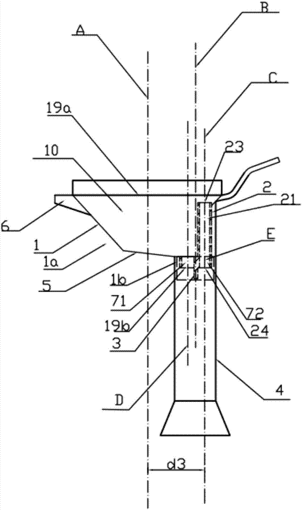
[0098] Embodiment 3: The following is attached Image 6 , Figure 7 , Figure 8 , Picture 12 , Figure 13 , Figure 14 To further explain the present invention:

[0099] A liquid taking part for a closed body fluid indwelling device, comprising a ring-shaped side wall A 1 and a ring-shaped side wall B 2.

[0100] The annular side wall armor 1 has an upper opening 11 and a lower opening 12. The annular side wall armour 1 includes an annular side wall armour upper part 1a, a bottom sealing plate 5 and an annular side wall armour lower part 1b. The annular side wall armour 1 encloses and forms a diversion channel 10. The liquid guiding channel 10 has a liquid inlet 19a and a liquid outlet 19b. The upper part 1a of the annular side wall is used for collecting liquid, the lower part 1b of the annular side wall is used to connect with the test tube, and the bottom sealing plate 5 is respectively connected with the upper part 1a of the annular side wall and the lower part 1b of the ann...


PUM


Abstract

The invention relates to a medical device, and especially relates to a device used for collecting a body fluid. The device is a fluid sampling member for a closed body fluid storage device, and comprises an annular sidewall A and an annular sidewall B; a flow guiding channel is formed by the annular sidewall A, and an air discharge channel is formed by the annular sidewall B; the upper portion of the annular sidewall B is not connected with the annular sidewall A, the minimum sectional area of the flow guiding channel is more than or equal to 3 mm<2> and less than or equal to 15 mm<2>; and the minimum sectional area of the air discharge channel is more than or equal to 3 mm<2> and less than or equal to 15 mm<2>. The device has the advantages of simplicity in processing, production cost reduction, high production efficiency, and prevention of backflow.

Description

Technical field [0001] The present invention relates to medical equipment, in particular to a device for collecting body fluids. Background technique [0002] The liquid taking part for a closed body fluid retainer in the prior art has only a diversion channel and no exhaust channel, especially when liquid is poured into a small-caliber container. When the liquid taking part and the connection part of the container are sealed and fitted, liquid retention often occurs. Even if the liquid taking part is provided with an exhaust channel, in the process of liquid guiding, there is still a phenomenon that the liquid will flow to the exhaust port and block the exhaust port, resulting in liquid retention. In addition, the liquid taking part is provided with an exhaust channel, but the production and processing are complicated, the cost is high, the production efficiency is low, and the flow diversion speed is not fast enough. Summary of the invention [0003] The purpose of the presen...

Claims


Application Information

Patent Timeline
Patent Type & Authority Applications(China)
IPC IPC(8): B01L3/00
CPCB01L3/56
Inventor 不公告发明人
Owner WUXI KAISHUN MEDICAL DEVICE MFG CO LTD
Why Eureka
Try Eureka