Powder energizing device

An energizing and powder technology, applied in the field of energizing devices and powder energizing devices, can solve the problems of multiple particle sizes, no human control, and no industrial standardization.

Pending Publication Date: 2017-07-18
杭州三得农业科技有限公司
View PDF0 Cites 0 Cited by
  • Summary
  • Abstract
  • Description
  • Claims
  • Application Information

AI Technical Summary

Problems solved by technology

[0003] The second reason is that the electrical polarity of energetic particle materials in nature is relatively single and cannot be controlled artificially; the particle size is diverse and cannot be standardized in the industry

Method used


Image

  • Powder energizing device

Examples


Embodiment 1

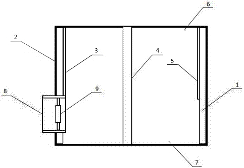
[0016] A powder energizing device, comprising a barrel-shaped casing 1 as an auxiliary electrode, the barrel-shaped casing 1 is wrapped with an insulating layer 2, and a conductive layer 3 is attached to the left side of the barrel-shaped casing 1; A main electrode 4 is provided in the middle of the casing 1, and a loop electrode 5 is attached to the right side inside the barrel-shaped casing 1, and an air outlet 6 and an air inlet blowing port 7 are respectively provided at the upper end and the lower end of the barrel-shaped casing 1.

[0017] In the present invention, the diameter of the preferred barrel-shaped casing 1 is 10-1000000000mm, and the length of the preferred barrel-shaped casing 1 is 10-100000000mm; meanwhile, in practical application, the length of the main electrode 4 is 1 / 1 of the barrel-shaped casing 1 10--1 / 5, the length of the main electrode 4 is 10-100000000mm, the number of the main electrode 4 is one or more than one, and less than ten. If the barrel-sh...

Embodiment 2

[0024] Barrel Energizer:

[0025] A, the barrel-shaped shell 1 is the auxiliary electrode, the diameter of the barrel is 10-1000000000mm, the shape of the end face of the barrel can be various geometric shapes, the length of the shell barrel is 10-100000000mm; the material of the barrel is all metal plates or meshes, and can also be The barrel outer layer is an insulator material, the barrel inner layer material is any conductive metal plate or net, and the material of the return electrode 5 can also be an inorganic conductive material, such as carbon fiber.

[0026] B, barrel center, main electrode 4, 1 / 10--1 / 5 shorter than the barrel, insulated from the loop electrode of the barrel shell, the diameter of the main electrode is 0.01-1000 mm smaller than the barrel, and the length is 10-100000000mm. When the diameter of the barrel is large, multiple main electrodes can be set; the main electrode material can be any conductive metal, or an inorganic conductive material, such as ...

Embodiment 3

[0031] When the concentration of harmful dust and harmful gas in the aerosol source is relatively large, the barrel energizer can be set to several levels until the concentration of harmful dust and harmful gas reaches the standard for harmless discharge.


PUM

PropertyMeasurementUnit
Diameteraaaaaaaaaa
Lengthaaaaaaaaaa

Abstract

The invention discloses a powder energizing device. The powder energizing device comprises a barrel-shaped shell which is used as an auxiliary electrode, wherein one insulating layer covers the barrel-shaped shell; a conducting layer is stuck at the left side in the barrel-shaped shell; a main electrode is arranged in the middle in the barrel-shaped shell; a loop electrode is stuck at the right side in the barrel-shaped shell; meanwhile, an air outlet and an air feeding and blowing opening are formed in the upper end and the lower end of the barrel-shaped shell respectively. By adopting the powder energizing device, energy continuation time of air particles, aerosol particles and nano dry fog particles can be prolonged through one set of closed loop equipment with an electric field loop, so that pneumatic particles can be transferred for a relatively long distance, and furthermore, the powder energizing device can play a decisive role in atmosphere source governance.

Description

technical field [0001] The invention relates to an energizing device, in particular to a powder energizing device, belonging to the technical field of powder processing equipment. Background technique [0002] There are many energetic particles in nature. For example, many suspended particles have electrons on them. However, because the energy of natural energetic particles is small and the yield is small, they cannot be used as basic energetic materials. This is one of them. [0003] The second reason is that the electrical polarity of energetic particle materials in nature is relatively single and cannot be controlled by humans; the particle size is diverse and cannot be standardized in the industry. Contents of the invention [0004] In view of the above problems, the present invention proposes a powder energizing device, which can energize mineral energy receiving particles and artificially manufactured energy receiving particles, and can meet people's various needs fo...

Claims


Application Information

Patent Timeline
IPC IPC(8): B01J19/08B01D46/02B08B15/04
CPCB01D46/02B01J19/087B08B15/04
Inventor 刘航远王爱新茆学华
Owner 杭州三得农业科技有限公司
Why Eureka
Try Eureka