Laser lighting device

A laser lighting and laser technology, applied in the field of lighting, can solve problems such as reducing the service life of laser LD, limiting the development of optical fiber lighting, and damage to laser LD, so as to improve light extraction efficiency and life of laser LD, improve lighting safety, and long service life Effect

Pending Publication Date: 2021-09-17
重庆云创江来光电科技有限公司
View PDF1 Cites 0 Cited by
  • Summary
  • Abstract
  • Description
  • Claims
  • Application Information

AI Technical Summary

Problems solved by technology

[0002] Traditional LED fiber optic lighting usually uses white light and plastic optical fiber. Because plastic optical fiber has a large loss of light, the transmission distance is short, and because white light is mixed with light of various wavelengths, the loss of each wavelength in the optical fiber during transmission Different, leading to the shift of light color after reaching the application end, which limits the development of fiber optic lighting to a certain extent
[0003] The patent document with the authorized announcement number CN105222021B discloses a laser electroless lighting system. Although the laser LD is used to realize it through the quartz optical fiber, the light output part adopts reflective excitation, and the excitation device adopts ceramic phosphor powder. The light efficiency obtained is low, and the light reflected by the ceramic phosphor powder into the optical fiber will damage the laser LD and reduce the service life of the laser LD

Method used


Image

  • Laser lighting device
  • Laser lighting device
  • Laser lighting device

Examples


Embodiment Construction

[0034] The following is further described in detail through specific implementation methods:

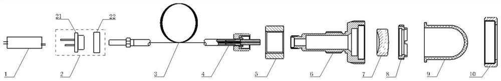
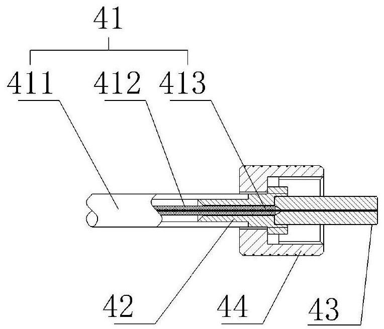
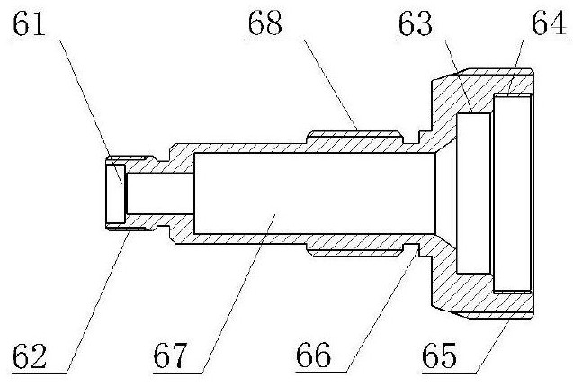
[0035] The reference signs in the drawings of the specification include: 1. power supply; 2. photoelectric conversion module; 21. laser chip; 22. optical system; 3. optical fiber group; 4. optical fiber connection terminal; 41. optical fiber; 411. optical fiber armor; 412, optical fiber tight sleeve layer; 413, bare optical fiber; 42, optical fiber tail handle; 43, ceramic ferrule; 44, ceramic core pressure ring; 5, nut; 6, laser excitation device firmware; 61, ceramic ferrule limit hole ; 62, ceramic core pressure ring connection thread; 63, lens limit hole; 64, lens pressure ring limit hole; 65, fluorescent cap pressure ring connection thread; 66, excitation seat limit ring; 67, inner cavity; 68, Excitation seat fixing thread; 7. Diffusion lens; 8. Lens pressure ring; 81. Fluorescent cap limit step; 82. Lens pressure ring connection thread; 83. Lens pressure ring tightening groove;...


PUM

PropertyMeasurementUnit
thicknessaaaaaaaaaa
lengthaaaaaaaaaa
diameteraaaaaaaaaa

Abstract

The invention belongs to the technical field of lighting, and particularly discloses a laser lighting device which comprises a power source, a photoelectric conversion module, an optical fiber set and a laser excitation device. The photoelectric conversion module converts a current into a laser; the optical fiber set is a transmission part, the output end of the optical fiber set is provided with an optical fiber connecting terminal, and the laser is transmitted to the laser excitation device through the optical fiber connecting terminal; the laser excitation device comprises a nut, a laser excitation device fixing piece, a diffusion lens, a lens pressing ring, a fluorescent cap and a fluorescent cap pressing ring. and the laser enters the inner cavity of the laser excitation device firmware, is converted by the diffusion lens, then irradiates the fluorescent cap and excites white light. The laser lighting device is high in light emitting efficiency, long in service life, high in safety and the like.

Description

technical field [0001] The invention belongs to the technical field of lighting, in particular to a laser lighting device. Background technique [0002] Traditional LED fiber optic lighting usually uses white light and plastic optical fiber. Because plastic optical fiber has a large loss of light, the transmission distance is short, and because white light is mixed with light of various wavelengths, the loss of each wavelength in the optical fiber during transmission The difference leads to the shift of light color after reaching the application end, which limits the development of fiber optic lighting to a certain extent. [0003] The patent document with the authorized announcement number CN105222021B discloses a laser electroless lighting system. Although the laser LD is used to realize it through the quartz optical fiber, the light output part adopts reflective excitation, and the excitation device adopts ceramic phosphor powder. The obtained light efficiency is low, an...

Claims


Application Information

Patent Timeline
Patent Type & Authority Applications(China)
IPC IPC(8): F21S2/00F21V5/00F21V8/00F21V9/30G02B6/00F21Y115/30
CPCF21S2/005F21V5/00F21V9/30G02B6/0006F21Y2115/30
Inventor 侯杰刘浪
Owner 重庆云创江来光电科技有限公司
Why Eureka
Try Eureka