Energy storage current transformer combination optimizing method based on maximum energy efficiency

An energy storage converter and combination optimization technology, which is applied in energy storage, AC network load balancing, photovoltaic power generation, etc., can solve problems such as the rare combination optimization of energy storage converters, achieve a simple combination method, and improve energy efficiency. Conversion efficiency and the effect of reducing energy loss

Active Publication Date: 2015-12-02
ELECTRIC POWER RESEARCH INSTITUTE, CHINA SOUTHERN POWER GRID CO LTD +3
View PDF1 Cites 5 Cited by
  • Summary
  • Abstract
  • Description
  • Claims
  • Application Information

AI Technical Summary

Problems solved by technology

However, the above-mentioned model method often only gives the total power value of the energy storage converter that needs to be configured for the configuration of the energy storage converter capacity, and does not combine the actual installation restrictions of the microgrid and the common energy storage converters on the market. The energy conversion efficiency curve of the energy storage converter is optimized reasonably, and the research on the combination optimization of the energy storage converter is relatively rare.

Method used


Image

  • Energy storage current transformer combination optimizing method based on maximum energy efficiency
  • Energy storage current transformer combination optimizing method based on maximum energy efficiency
  • Energy storage current transformer combination optimizing method based on maximum energy efficiency

Examples


Embodiment 1

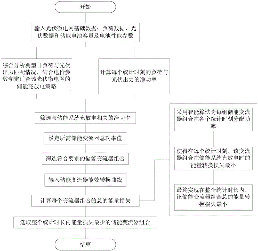
[0033] figure 1 It is a flow chart of the energy storage converter combination optimization method based on energy efficiency maximization in this embodiment.

[0034] The basic steps of the energy storage converter combination optimization method based on energy efficiency maximization in this embodiment are:

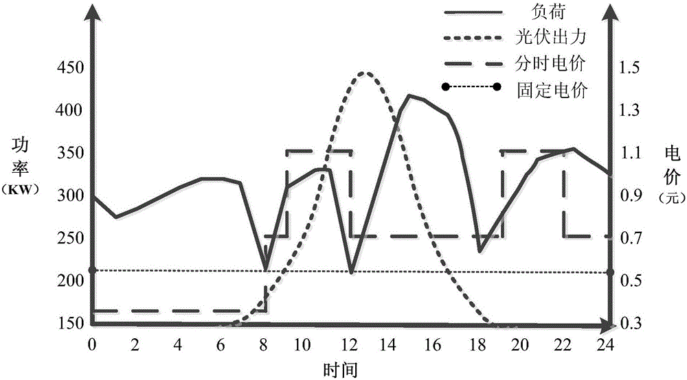
[0035] Step 1 (A): Input the basic data of the photovoltaic microgrid, the basic operating data is the microgrid load data P L and PV output data P PV . The time length of the input data is T, and the time interval of the data is ΔT. In order to ensure that the obtained net power can be more comprehensive and accurately close to the actual operation of the microgrid, the following constraints need to be satisfied

[0036] T > T m i n ...


PUM


Abstract

The invention provides an energy storage current transformer combination optimizing method based on maximum energy efficiency. The method includes the following steps: A, inputting basic data of a photovoltaic micro-grid; B, calculating the load within all sampling intervals [delta]T and the net power of photovoltaic output according to load data and photovoltaic output data in the step A; setting the required total power PC of an energy storage current transformer according to a net power value P0' obtained in the step B and associated with the charge and discharge process of an energy storage system and also according to the maximum energy storage charge and discharge power PBmax; D, calculating all current transformer combinations that meet requirements according to optional current transformer specifications and the total power of the current transformer determined in the step C; E, adopting a smart algorithm to distribute power to each current transformer combination determined in the step D within each period of time relative to each current transformer in the combination according to the net power value P0' obtained in the step B and associated with the charge and discharge process of the energy storage system and also to the configured the total power PC of the energy storage current transformer; and F, selecting the current transformer combination the loss of which is the minimum within a whole counted period of time in the step E as a final energy storage current transformer combination scheme.

Description

technical field [0001] The invention relates to an energy storage converter combination optimization method based on energy efficiency maximization. Background technique [0002] In recent years, with the increase of government subsidies for photovoltaic industry policies and the significant drop in the price of photovoltaic modules, more and more investors have introduced photovoltaic microgrid power generation models into various fields. The popularization of the photovoltaic micro-grid model can greatly reduce the dependence of the industrial field on traditional fossil energy, and has significant energy-saving and environmental protection benefits. [0003] In order to ensure the reliability of micro-grid power supply and maximize the use of photovoltaic resources, it is usually necessary to configure appropriate energy storage for the micro-grid system. At this stage, due to the high price of energy storage devices, the configuration of energy storage capacity should n...

Claims


Application Information

Patent Timeline
Patent Type & Authority Applications(China)
IPC IPC(8): H02J3/32H02J3/38
CPCY02E10/56Y02E70/30
Inventor 田兵雷金勇许爱东郭晓斌喻磊马溪原许健刘念杨苹许志荣周少雄
Owner ELECTRIC POWER RESEARCH INSTITUTE, CHINA SOUTHERN POWER GRID CO LTD
Why Eureka
Try Eureka