Wheel hub flywheel-motor kinetic hybrid system and method

a technology of kinetic hybrid system and flywheel, which is applied in the direction of battery/fuel cell control arrangement, electric devices, propulsion by batteries/cells, etc., can solve the problems of limiting the efficiency of electric vehicles and hybrids, and reducing vehicle performance and acceleration. , the effect of reducing emissions

Inactive Publication Date: 2012-06-28
HE JING +1
View PDF15 Cites 66 Cited by
  • Summary
  • Abstract
  • Description
  • Claims
  • Application Information

AI Technical Summary

Benefits of technology

[0010]The present invention offers the following advantages over conventional electric vehicles and electric hybrids. The primary improvement over the prior art is in energy efficiency and the reduction of emissions by virtue of improved fuel efficiency. Because the flywheel stores energy in kinetic form, which is the same form of energy the vehicle uses, many energy conversion stages are avoided compared to electric vehicles and electric hybrids, reducing energy losses due to conversion quite significantly. Furthermore, many transmission line losses can be avoided or minimized by installing the flywheel and its variator motor / generator into the wheel hub to directly accelerate the wheel and / or recover energy from the wheel. A second area of improvement is in the vehicle's performance, as the flywheel provides power at a higher power density than either motor / generators or batteries can provide. The power transmitted with the system is greater than the power of the motor / generator, so the vehicle's accelerative performance is improved. Another advantage is that the present invention can reduce the cost of the hybrid vehicle. Because the flywheel is responsible for the majority of the energy stored and released, the vehicle is less dependent on the battery pack, and the rate of charge / discharge as well as the number of charge / discharge cycles can be reduced, extending the battery life, which also reduces the cost of ownership over the life of the vehicle. With the extra power provided by the flywheel, the power requirements on motor / generators and inverter / controllers can be reduced, which also reduces the cost of manufacture. Integrating the flywheel into the wheel hubs of a vehicle makes for more flexibility, which can reduce design costs, so the present invention is also an improvement over flywheel hybrids of the prior art. If the present invention is used in an electric vehicle, it can also increase the vehicle's range per charge because of better efficiency.

Problems solved by technology

Traditional electric vehicles and electric hybrid vehicles face the same set of challenges and / or limitations.
First, because energy is stored in a chemical form in batteries, which differs from the mechanical, kinetic form of energy the vehicle ultimately uses, the energy stored and reused must undergo several stages of conversion.
From mechanical to electric, from electric to chemical, from chemical to electric, and from electric to mechanical again, a typical path for reusing energy recovered from regenerative braking, the energy undergoes four conversions, resulting in significant energy losses due to conversion.
Only a small portion of regenerated energy can be reused, which limits the efficiency of electric vehicles and hybrids.
Second, the power density of both motor / generators and batteries are not high enough, which restricts vehicle performance and acceleration.
Moreover, with current battery technologies, battery life is a significant consideration; since the number of charge / recharge cycles the battery can undergo is limited, this results in a need to replace the battery pack after some time, adding to the cost of owning the hybrid vehicle.
Additionally, for electric vehicles, the distance the vehicle can travel per charge is relatively short.
There exist mechanical continuously variable transmissions to control the storage and release of energy in a flywheel hybrid vehicle, but these mechanical CVTs suffer low efficiency at a high transmission ratio.
Demanding high energy capacities in the flywheel necessitates high flywheel speeds, which adds safety issues, not to mention that the energy in the flywheel is not used during cruise.
More importantly, using electromagnetic means to control the transfer of energy to and from the flywheel makes it so that 100 percent of the energy stored into the flywheel must undergo conversion, limiting efficiency.
The prior art has not sufficiently used the advantages of the flywheel while avoiding its disadvantages for flywheel hybrids to be industrially competitive.

Method used


Image

  • Wheel hub flywheel-motor kinetic hybrid system and method
  • Wheel hub flywheel-motor kinetic hybrid system and method
  • Wheel hub flywheel-motor kinetic hybrid system and method

Examples


first embodiment

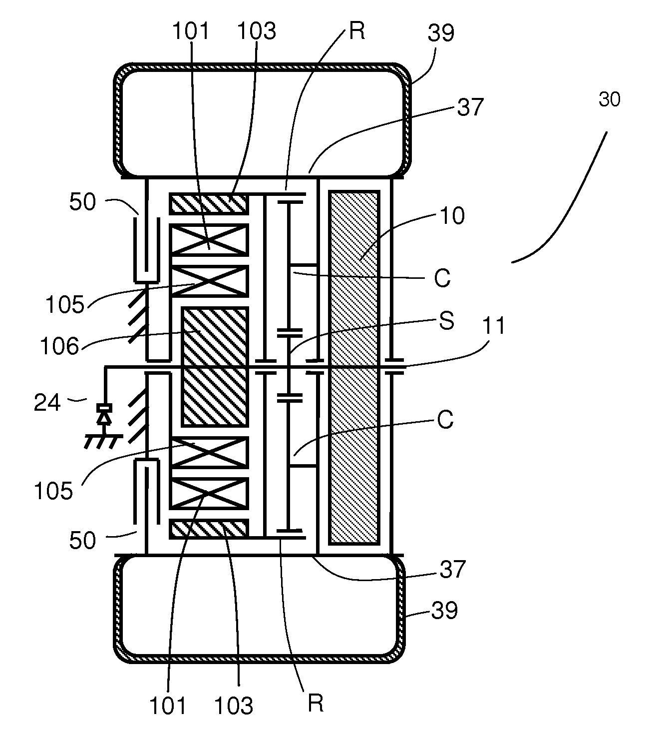
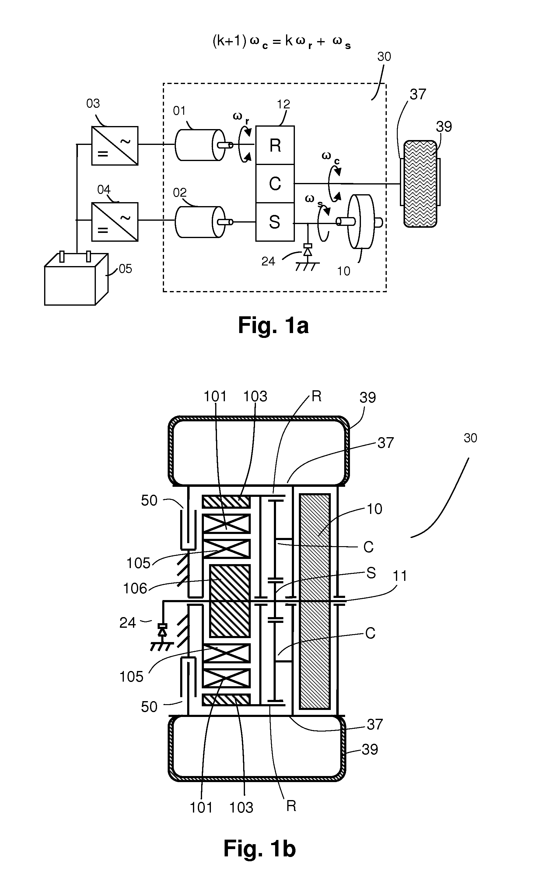
[0022]FIG. 1(a) is a schematic for the mechanical components of the The planetary gear set 12 connects the flywheel 10, the motor / generators 01 and 02, as well as the wheel rim 37, into a three port kinetic-electric hybrid power-split system. The first port of the planetary gear set 12 (for instance, the sun gear S) connects to the flywheel 10; the second port (for instance, the ring gear R) connects to the variator motor / generator 01; the third port (for instance, the planet carrier C) connects to the wheel rim 37 inside the tire 39. The other motor / generator 02 shares the first port S with the flywheel 10 and a one-way clutch 24, which prevents the flywheel 10 from rotating in the reverse direction. The primary power source is provided by the motor / generators 01 and 02 powered by the battery pack 05 through the controller / inverters 03 and 04, respectively supplying 01 and 02 with energy. The secondary power source and the secondary energy storage are provided by the flywheel 10.

[...

second embodiment

[0053]FIG. 9(b) illustrates the structure of the present invention if a magnetic planetary gear system is used. In this case, the connections among the flywheel 10b, the rotor 103b and stator 101b of the motor / generator 01, and the magnetic gears MS, MR and MC are the same as what was shown in FIG. 8(b). The difference to note here is that the rotor 106b of the motor / generator 02 is connected to the wheel hub 37b and not to the flywheel 10b. FIGS. 9(a) and 9(b) can be controlled to be functionally equivalent.

third embodiment

[0054]FIG. 10(b) depicts a magnetic planetary gear system implementation of the The connections among the flywheel 10b, the rotor 103b and stator 101b of the motor / generator 01, and the magnetic gears MS, MR and MC are the same as in FIGS. 8(b) and 9(b). The difference between the configurations in FIGS. 9(b) and 10(b) is that in FIG. 10(b) the motor / generator 02 has been installed in another wheel hub (not shown). FIGS. 10(a) and 10(b) both show the structure of the group of components represented by 32 in FIG. 4(a). FIG. 10(a) presents a configuration using a mechanical planetary gear system while FIG. 10(b) presents a configuration using a magnetic planetary gear system; the two configurations are functionally equivalent.

[0055]FIG. 10(c) shows an implementation of the second wheel hub of the third embodiment containing the group of components 34c, which includes the motor / generator 02, using a mechanical planetary gear system. FIG. 10(c) is functionally equivalent to the structu...


PUM


Abstract

System and method for the combination of a flywheel and motor/generator inside a wheel hub for hybrid vehicle propulsion. The flywheel and motor/generator are connected by a planetary gear system, in which a first port is connected to the flywheel, a second port is connected to the wheel hub, and a third port is connected to a motor/generator. An additional motor/generator may be used at one of the first port and second port. The system may be used in an electric-kinetic hybrid mode, or in a fuel-kinetic hybrid mode, when used in a vehicle having an internal combustion engine as the prime mover. Efficiency of energy storage and release is significantly improved in comparison to prior art.

Description

BACKGROUND OF THE INVENTION[0001]1. Field of the Invention[0002]This invention pertains to a system and method for a combination of a flywheel and motor / generator(s) contained within a wheel hub used for hybrid vehicle propulsion. The system may be used in conjunction with electric vehicles for an electric-kinetic hybrid vehicle, or used in conjunction with vehicles powered by internal combustion for a fuel-kinetic hybrid vehicle.[0003]2. Description of the Related Art[0004]Traditional electric vehicles and electric hybrid vehicles face the same set of challenges and / or limitations. First, because energy is stored in a chemical form in batteries, which differs from the mechanical, kinetic form of energy the vehicle ultimately uses, the energy stored and reused must undergo several stages of conversion. From mechanical to electric, from electric to chemical, from chemical to electric, and from electric to mechanical again, a typical path for reusing energy recovered from regenerative...

Claims


Application Information

Patent Timeline
Patent Type & Authority Applications(United States)
IPC IPC(8): B60K7/00
CPCY02T10/6204B60K6/105B60K2007/0092B60K17/046B60K2007/0038B60K7/0007B60K2007/003B60L15/2054B60L2210/40B60L2220/44B60L2240/12B60L2240/421B60L2240/423B60L2240/486B60L2240/507B60L2260/28B60L50/16B60L50/30B60L50/61B60L50/66B60L58/21Y02T10/62Y02T10/64Y02T10/70Y02T10/7072Y02T10/72
Inventor HE, JINGHE, HONGPING
Owner HE JING
Why Eureka
Try Eureka