

Heat exchanger
a heat exchanger and heat exchanger technology, applied in indirect heat exchangers, lighting and heating apparatuses, laminated elements, etc., can solve the problems of reducing the size, affecting the efficiency of heat exchangers, so as to improve the thermal efficiency and prevent the effect of pressure drop
- Summary
- Abstract
- Description
- Claims
- Application Information
AI Technical Summary
Benefits of technology
Problems solved by technology
Method used
Image

Examples
Embodiment Construction
[0040]Reference will now be made in detail to exemplary embodiments of the present invention, examples of which are illustrated in the accompanying drawings, wherein like reference numerals refer to the like elements throughout. Exemplary embodiments are described below to explain the present invention by referring to the figures.
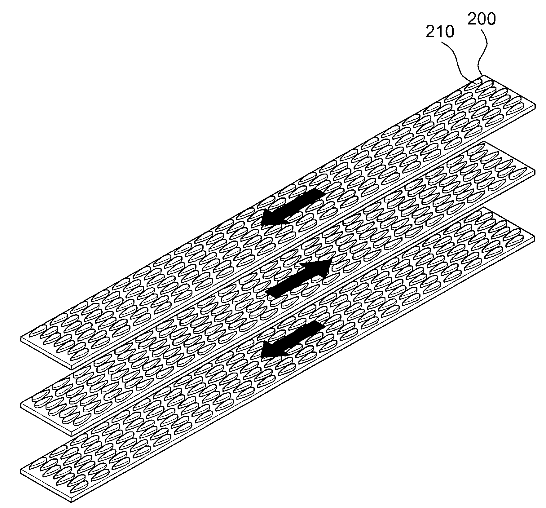
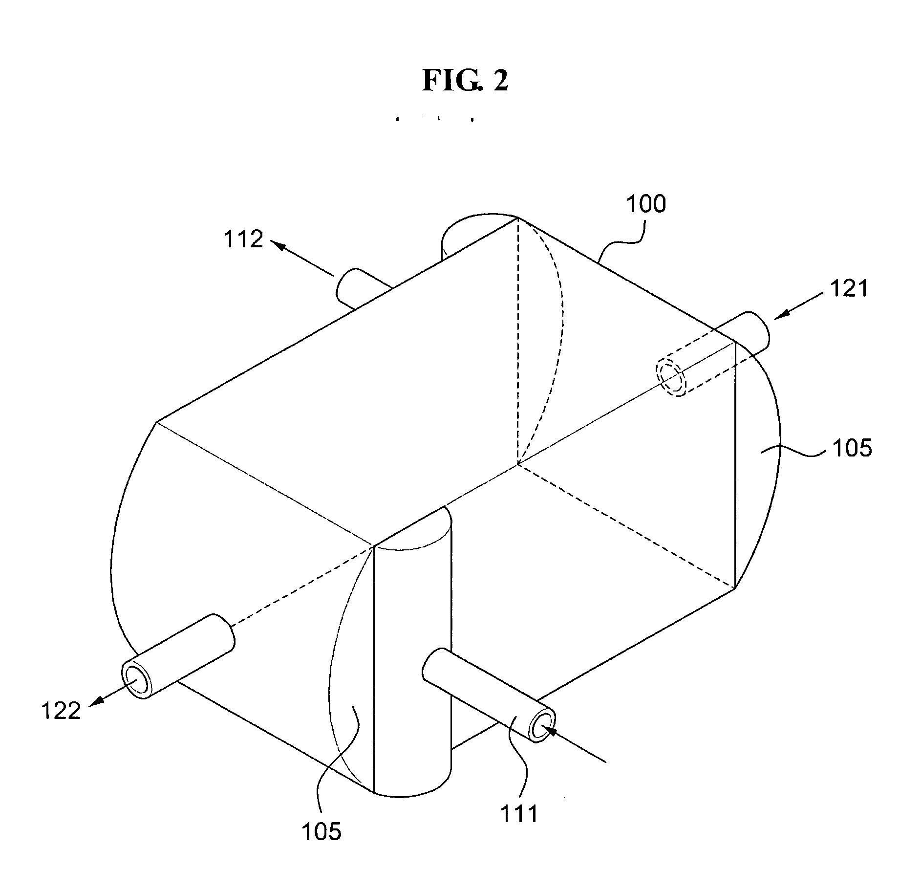
[0041]FIG. 2 is a perspective view illustrating a heat exchanger according to example embodiments of the present invention, FIG. 3 is an exploded perspective view illustrating a plurality of plates 200 of a heat exchanger according to example embodiments of the present invention, and FIG. 4 is a perspective view illustrating a plate of FIG. 3.
[0042]The heat exchanger includes a housing 100 receiving the plurality of plates 200 therein, a header portion 105 disposed on both sides of the housing 100, inflow pipes 111 and 121 of a heat exchange fluid, and outflow pipes 112 and 122 of the heat exchange fluid. In this instance, the plurality of plates 200 includ...
PUM
 Abstract
Description
Claims
Application Information