Engine for a vehicle

Active Publication Date: 2005-03-03
YAMAHA MOTOR CO LTD
View PDF2 Cites 9 Cited by
  • Summary
  • Abstract
  • Description
  • Claims
  • Application Information

AI Technical Summary

Benefits of technology

[0007] An advantage of this invention is to provide an engine for a vehicle capable of effecting cost reduction due to a layout

Problems solved by technology

In a system with piping such as a separate delivery pipe as described above, it is necessary that interference with other membe

Method used


Image

  • Engine for a vehicle
  • Engine for a vehicle
  • Engine for a vehicle

Examples


Embodiment Construction

[0030] Although an embodiment of the engine for a vehicle of this invention will be described below with reference to the drawings, this invention is not limited to this embodiment. Also, the embodiment of this invention shows a best mode of the invention and technical terms of this invention are not limited to those used herein.

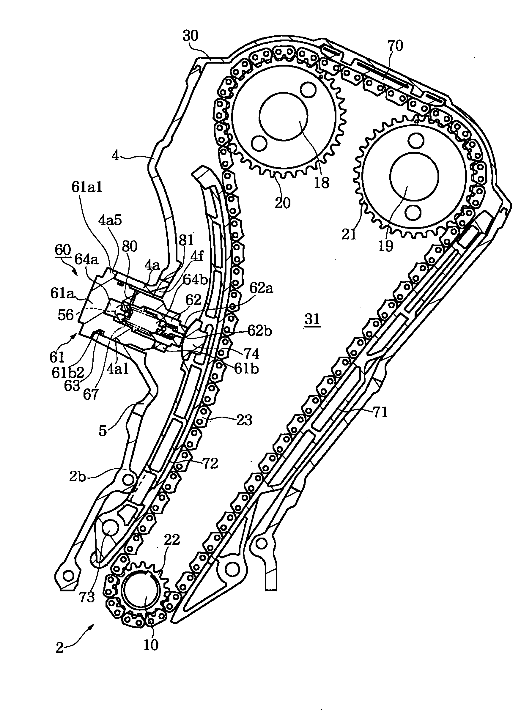
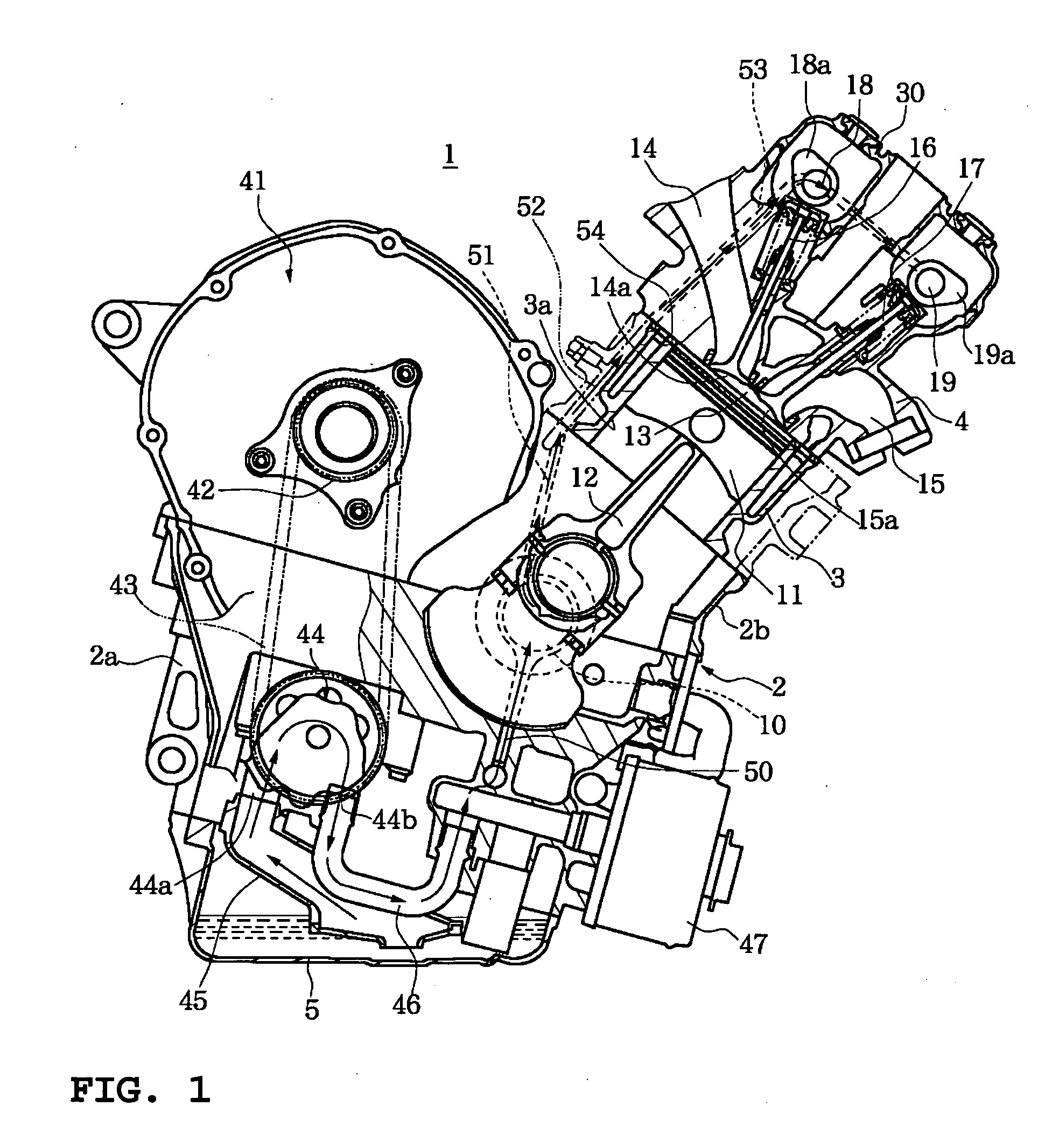
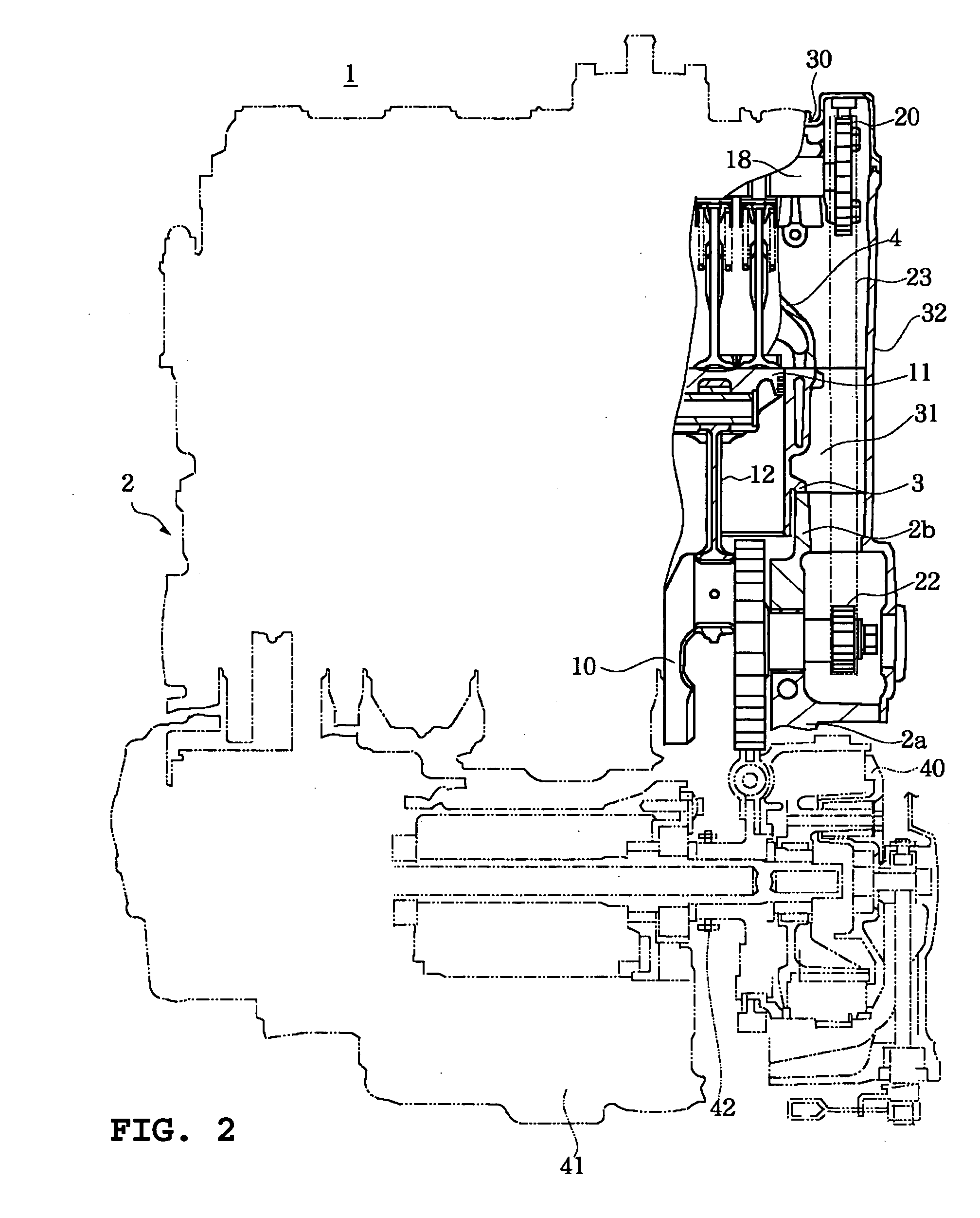
[0031]FIG. 1 is a side view of an in-line multi-cylinder engine in a posture when mounted on a vehicle. FIG. 2 is a sectional view of a cam chain chamber of the in-line multi-cylinder engine. FIG. 3 is a side view of the cam chain chamber of the in-line multi-cylinder engine. FIG. 4 is a plan view of the mounting portion of a cam chain tensioner. FIG. 5 is a sectional view taken along the line V-V of FIG. 4. FIG. 6 is a sectional view showing an orifice in a lubricating oil passage.

[0032] An engine for a vehicle 1 in this embodiment has a crankcase 2, a cylinder block 3 and a cylinder head 4. The crankcase 2 includes a lower case 2a and an upper case 2b, a...


PUM


Abstract

An engine for a vehicle includes a cam chain tensioner actuated by pressure of lubricating oil for stabilizing a movement of a cam chain, a lubricating oil passage through which the lubricating oil is supplied to cam shafts in a cylinder head and a branched lubricating oil passage, branched from the lubricating oil passage, through which the lubricating oil is supplied to the cam chain tensioner. The branched lubricating oil passage is branched from the lubricating oil passage at a portion on an upstream side of an orifice in the lubricating oil passage located upstream of the cylinder head, and in communication with the cam chain tensioner.

Description

BACKGROUND OF THE INVENTION [0001] 1. Field of the Invention [0002] This invention relates to an engine for a vehicle with a cam chain tensioner actuated by the pressure of lubricating oil for stabilizing the movement of a cam chain. [0003] 2. Description of Related Art [0004] In an engine for a vehicle for transmitting rotation of a crankshaft to cam shafts, a system has been known in which a cam chain tensioner using a plunger adapted to be pushed out by oil pressure, is provided to stabilize the movement of a cam chain. [0005] In some cam tenioners of this type, a passage through which lubricating oil is supplied to the cam tensioner, is provided with a delivery pipe separate from a crankcase and lubricating oil is supplied to the cam chain tensioner through the delivery pipe. In a system with piping such as a separate delivery pipe as described above, it is necessary that interference with other members is avoided, which places restrictions on the layout and increases the number...

Claims


Application Information

Patent Timeline
IPC IPC(8): F02B67/06F01L1/02F01M1/06F01M9/10F01M11/00F01M11/02F02B61/02F16H7/08F16H57/035F16H57/04
CPCF01L1/02F01L2001/0537F01M9/10F01M11/02F16H2007/0859F16H7/0836F16H2007/0806F16H2007/0812F02B61/02
Inventor OKAZAWA, GOICHI
Owner YAMAHA MOTOR CO LTD
Why Eureka
Try Eureka