
Process for sifting a mixture of a milled material and a fluid, and mill sifter

A classifier and grinding machine technology, applied in the direction of classification, chemical instruments and methods, and devices whose axial direction of the swirling flow can be reversed, etc., can solve problems such as pressure loss in the production system of finished materials that affect the smooth operation of the mill

Inactive Publication Date: 2011-07-13
LOESCHE GMBH
View PDF20 Cites 11 Cited by
  • Summary
  • Abstract
  • Description
  • Claims
  • Application Information

AI Technical Summary

Problems solved by technology

For example, the classification process affects the smooth operation of the mill, the throughput of finished material and the pressure loss of the entire system

Method used


Image

  • Process for sifting a mixture of a milled material and a fluid, and mill sifter
  • Process for sifting a mixture of a milled material and a fluid, and mill sifter
  • Process for sifting a mixture of a milled material and a fluid, and mill sifter

Examples


Embodiment Construction

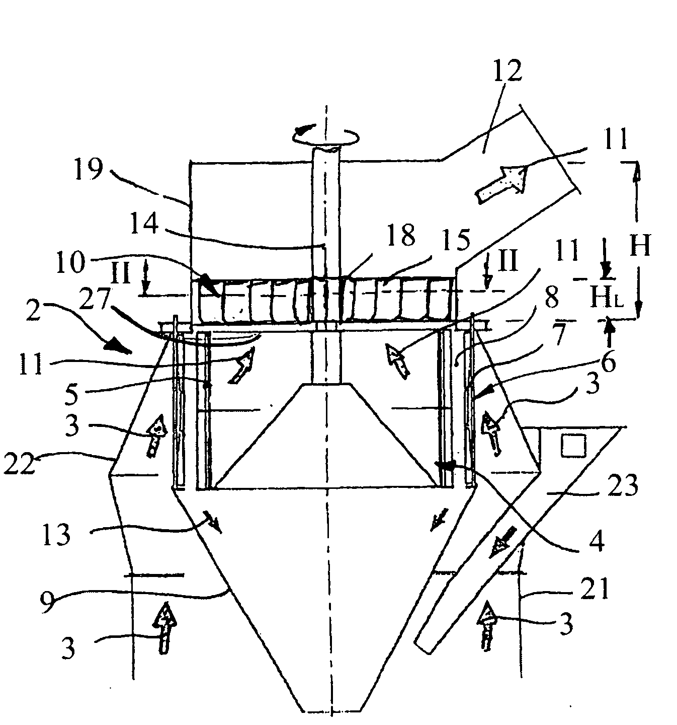
[0045] figure 1 The mill classifier 2 integrated with the roller mill is shown. Only the upper region of the mill housing 21 of the roller mill is shown, with the side grinding stock supply 23 . The classifier housing 22 is connected to the grinding material housing 21 .

[0046] The mill classifier 2 comprises a dynamic classifier part 4 which in this embodiment is a bar rotor or a rotor with rotor blades 5 arranged coaxially around a rotor axis 14 . A guide vane ring 6 with guide vanes 7 is arranged coaxially to the dynamic classifier part 4 , the guide vanes 7 being stationary and adjustable. The ground material fluid mixture 3 from the grinding chamber enters the classifying chamber 8 in swirling flow from the grinding chamber, where the coarse material particles 13 are separated and supplied via the sand cone 9 as coarse material discharge for regrinding.

[0047] The fine material fluid flow 11 (also called dust gas mixture) enters the classifier outlet housing 19 thr...


PUM


Abstract

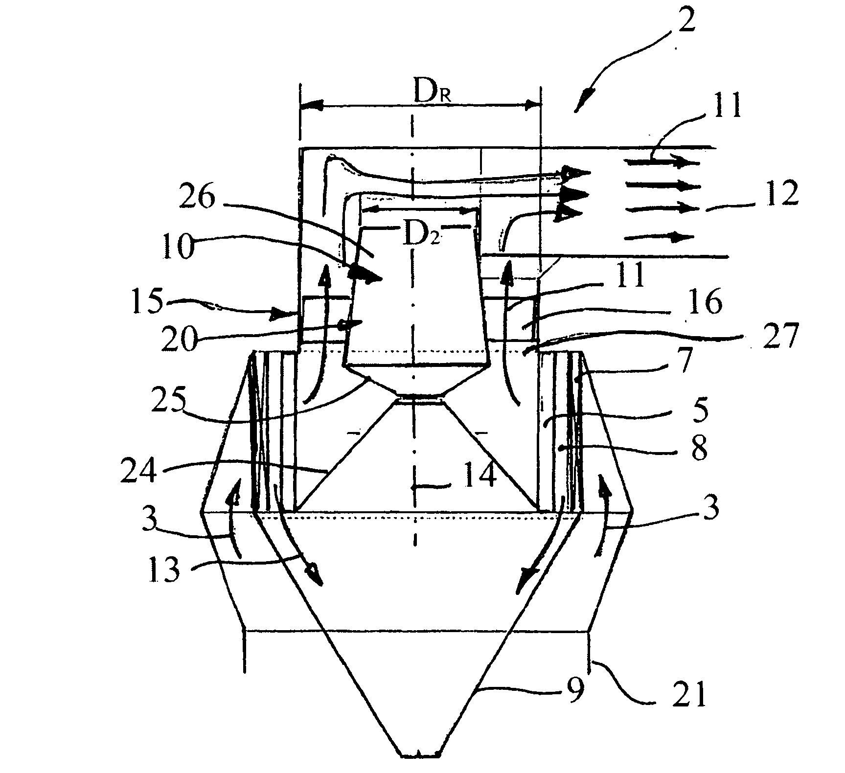
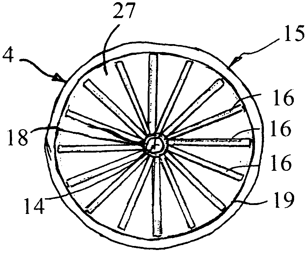
The invention relates to a method for sifting a mixture of milled material and a fluid and to a mill sifter, in particular for carrying out the process according to the invention. To improve the milling-sifting process and the subsequent dust separation and, in particular, to optimize the energy balance of a milling installation, it is envisaged according to the invention not only to reduce or eliminate the swirling of the stream of fine material and fluid emerging with an angular momentum from the dynamic part of the sifter but also to make it more uniform and deflect it into a virtually linear flow with the aid of a distributor (15) and a displacer (20) in a sifter outlet housing. The fixed distributor (15), arranged coaxially in relation to the axis of the sifter (20) in the sifter outlet housing, and the displacer may be formed as one unit and the directing elements of the distributor may be arranged on the displacer, reaching almost as far as the inner wall of the sifter outlet housing.

Description

technical field [0001] The invention relates to a method for classifying a ground material-fluid mixture according to the preamble of claim 1 and a grinder-classifier for carrying out the method according to the preamble of claim 6 . [0002] The invention is particularly applicable to roller mill classifiers, which may be integral with or provided in vertical roller mills or roller mills, such as air-swept roller mills (such as wind-swept roller mill). Background technique [0003] A classifier typically has a dynamic classifying member, such as a bar or bladed rotor, and static guide vanes, arranged in a ring around the dynamic classifying member, forming a classifying chamber or zone. The ground stream mixture reaches the classifying chamber in an upwardly directed spiral flow close to the housing, where the coarse particles are separated and poured back into the grinding chamber by the sand cone for regrinding. The fine material reaching the belt rotor is fed into the ...

Claims


Application Information

Patent Timeline
Patent Type & Authority Applications(China)
IPC IPC(8): B07B7/083
CPCB07B7/083B07B13/11B04C5/12
Inventor 安德烈·贝茨迈克尔·克思奈
Owner LOESCHE GMBH
Learn More