
Lifting umbrella transmission device

A technology of transmission device and transmission mechanism, which is applied in the direction of walking sticks, etc., which can solve the problems of large manual force and inconvenience, especially for children or the elderly, or even the inability to open the umbrella, and large force, so as to achieve the effect of improving stability

Pending Publication Date: 2021-02-26
周杰龙
View PDF0 Cites 0 Cited by
  • Summary
  • Abstract
  • Description
  • Claims
  • Application Information

AI Technical Summary

Problems solved by technology

[0003] The structures of the large-scale folding sun umbrellas and princess pagoda umbrellas used outdoors on the existing market make it necessary to push or pull the umbrellas with external force. The manual force is large and inconvenient to use. Its main defect is not to open the umbrella. Another structure of the umbrella is that the top plate and the groove bone are connected by steel wires to drive the retraction and opening of the umbrella surface, which not only requires a lot of force, but also shakes left and right. , overturned in strong winds, or even unusable, the above-mentioned umbrellas and princess pagoda umbrellas will bring inconvenience to use. The service life of large umbrellas is usually not high

Method used


Image

  • Lifting umbrella transmission device
  • Lifting umbrella transmission device
  • Lifting umbrella transmission device

Examples


Embodiment Construction

[0018] use Figure 1-Figure 4 A parachute transmission device according to an embodiment of the present invention is described as follows.

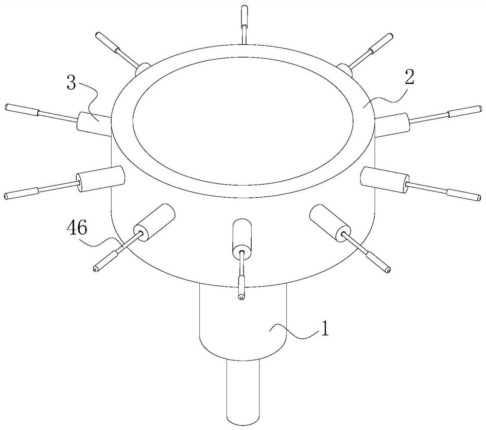
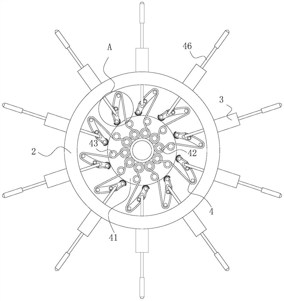
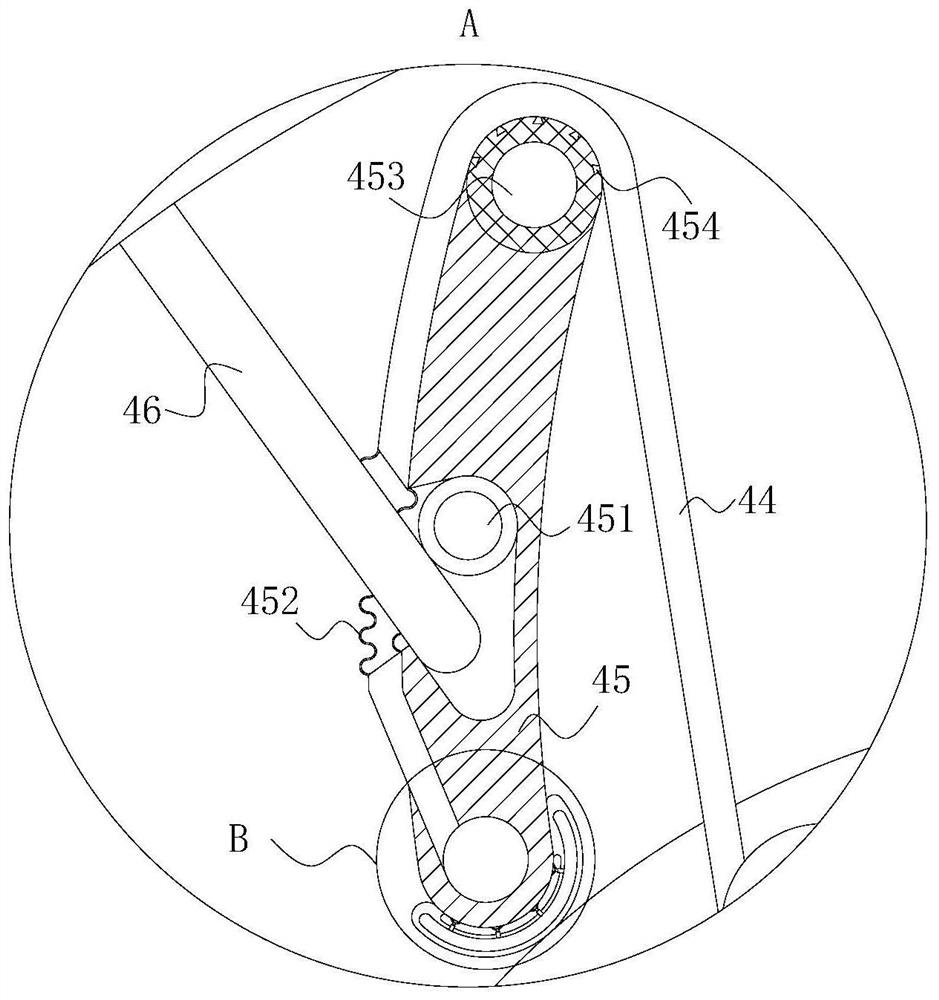
[0019] Such as Figure 1-Figure 4 As shown, a parachute transmission device according to the present invention includes a rotating shaft 1, a mounting ring 2, a mounting pipe 3 and a transmission mechanism 4; the lower end of the rotating shaft 1 is rotatably connected to the motor, and the upper end of the rotating shaft 1 is rotatably connected to the In the wall of the installation ring 2; the outer wall of the installation ring 2 is evenly fixed and horizontally connected with the installation pipe 3, and the inside of the installation ring 2 is provided with a transmission mechanism 4; the transmission mechanism 4 includes a gear plate 41, a differential lever 42, and connecting rod 43, connecting rope 44, arc-shaped plate 45 and support rod 46; the gear plate 41 is fixedly connected to the upper end of the rotating shaft 1, and the...


PUM


Abstract

The invention belongs to the technical field of folding sun-rain umbrella devices, and particularly relates to a lifting umbrella transmission device, which comprises a rotating shaft, a mounting ring, a mounting pipe and a transmission mechanism. The lower end of the rotating shaft is rotationally connected to the motor, and the upper end of the rotating shaft is rotationally connected into the wall of the mounting ring; mounting pipes are uniformly, fixedly and horizontally connected to the outer wall of the mounting ring, and a transmission mechanism is arranged in the mounting ring; the transmission mechanism comprises a gear disc, a differential rod, an adapter rod, a connecting rope, an arc-shaped plate and a supporting rod; the gear disc is fixedly connected to the upper end of therotating shaft, and a differential rod is annularly arranged on the upper surface of the gear disc; when the motor is started, the rotating shaft can be driven to rotate, when the rotating shaft rotates, the gear disc at the upper end of the rotating shaft can be driven to rotate, when the gear disc begins to rotate, the differential rod begins to rotate, then the connecting rope is wound, the arc-shaped plate is pulled to begin to rotate, namely, the supporting rod begins to be pushed to slide towards the outer side of the mounting pipe, umbrella fabric is unfolded, and an umbrella can be unfolded automatically.

Description

technical field [0001] The invention belongs to the technical field of folding umbrella devices, in particular to a transmission device for a lifting umbrella. Background technique [0002] Umbrellas are umbrellas that are used to shade the sun on sunny days and from the rain on rainy days. It is an umbrella that can be used in sunny and rainy days, and can be used for both sunshade and rain. Generally, it is a light-colored umbrella with sun protection function, but the umbrella basically has no anti-ultraviolet effect. [0003] The structures of the large-scale folding sun umbrellas and princess pagoda umbrellas used outdoors on the existing market make it necessary to push or pull the umbrellas with external force. The manual force is large and inconvenient to use. Its main defect is not to open the umbrella. Another structure of the umbrella is that the top plate and the groove bone are connected by steel wires to drive the retraction and opening of the umbrella surfac...

Claims


Application Information

Patent Timeline
IPC IPC(8): A45B25/00
CPCA45B25/00A45B2025/003
Inventor 周杰龙
Owner 周杰龙
Learn More