Heat Exchanger Assembly

a technology of heat exchanger and assembly, which is applied in the direction of tubular elements, lighting and heating apparatus, and stationary conduit assemblies, etc., can solve the problems of negatively affecting the performance of the heat exchanger, and achieve the effect of avoiding pressure drop penalties, maximizing the length of the louvers, and preventing the legs from collapsing

Inactive Publication Date: 2011-03-03
DELPHI TECH INC
View PDF12 Cites 8 Cited by
  • Summary
  • Abstract
  • Description
  • Claims
  • Application Information

AI Technical Summary

Benefits of technology

[0007]The legs of the air fins are angled to maintain the structural integrity of the heat exchanger, i.e. to prevent the legs from collapsing during the manufacturing or use of the heat exchanger. However, the maximum angle is set at 4 degrees to maximize the length of the louvers on the legs of the air fin, and thereby avoid a pressure drop penalty, which results from having shorter louvers. Such a pressure drop negatively impacts the performance of the heat exchanger. Additionally, the angled legs improve the ability of the heat exchanger to shed water.
[0008]The lead-in and exit radii are minimized in order to maximize the length of the louvers, and thereby limit the pressure drop penalty explained above. However, the lead-in and exit radii must be la

Problems solved by technology

Such a pressure drop negatively impacts

Method used


Image

  • Heat Exchanger Assembly
  • Heat Exchanger Assembly
  • Heat Exchanger Assembly

Examples


Embodiment Construction

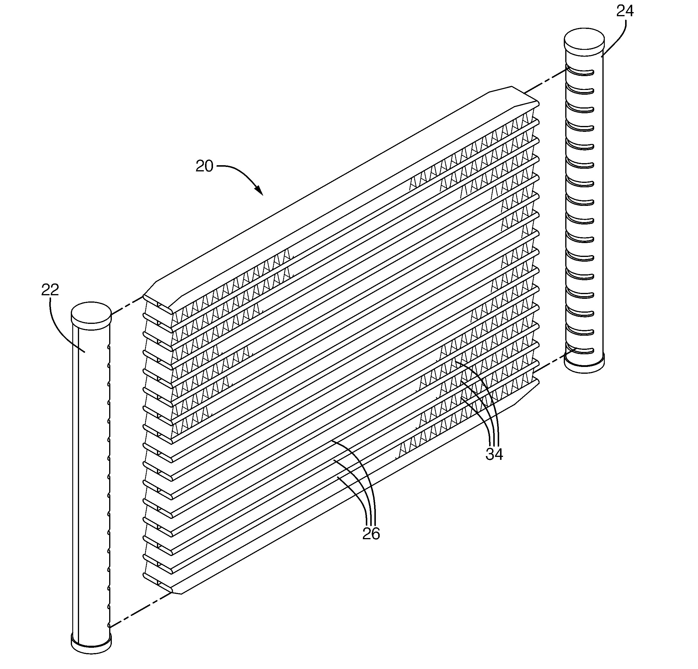
[0014]Referring to the Figures, wherein like numerals indicate corresponding parts throughout the several views, a heat exchanger assembly 20 for transferring heat between a coolant and a flow of air is generally shown in FIG. 1. The heat exchanger assembly 20 has a number of uses, including but not limited to use as a: radiator, condenser, heater, evaporator, chiller or cooler.

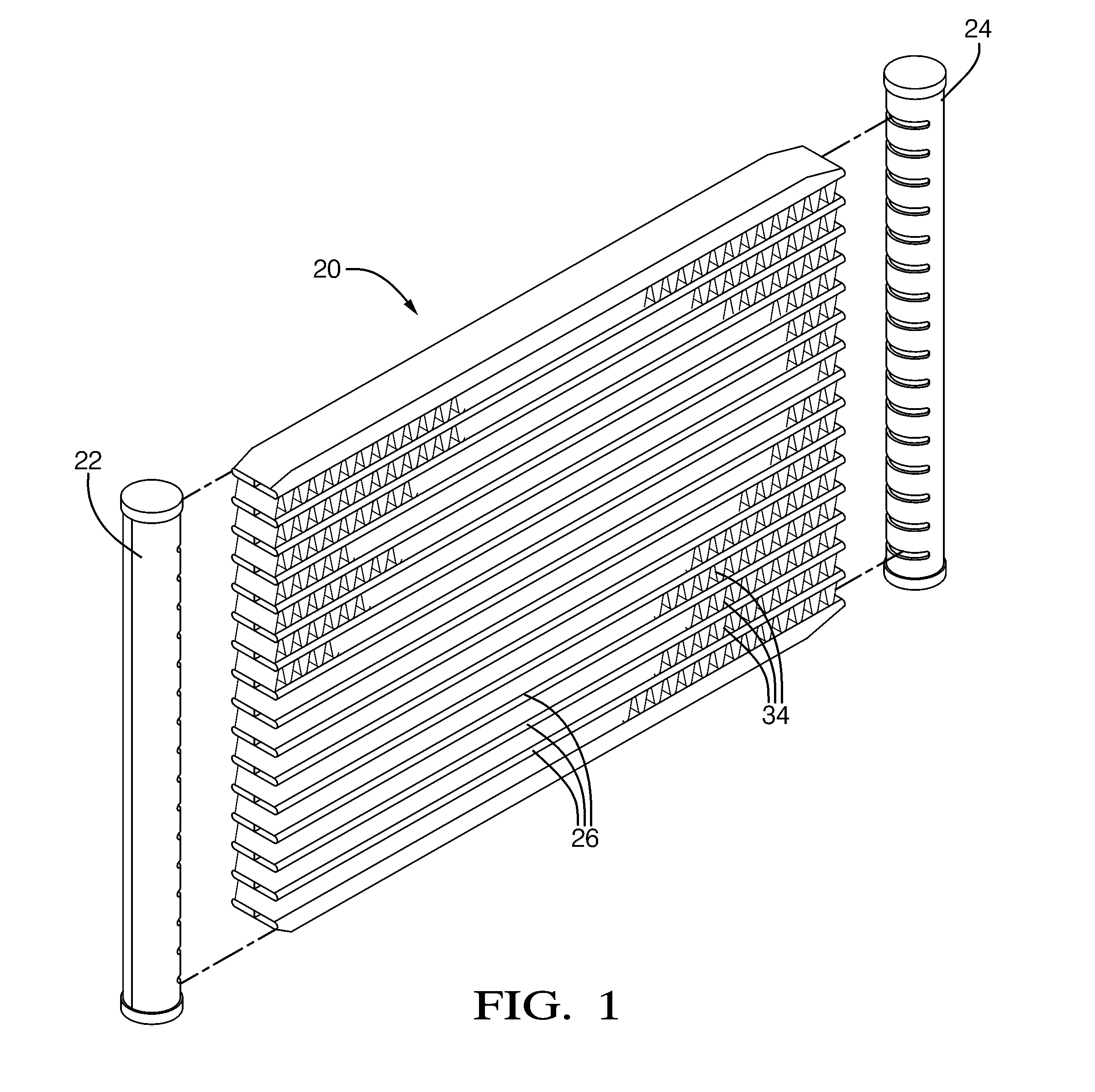
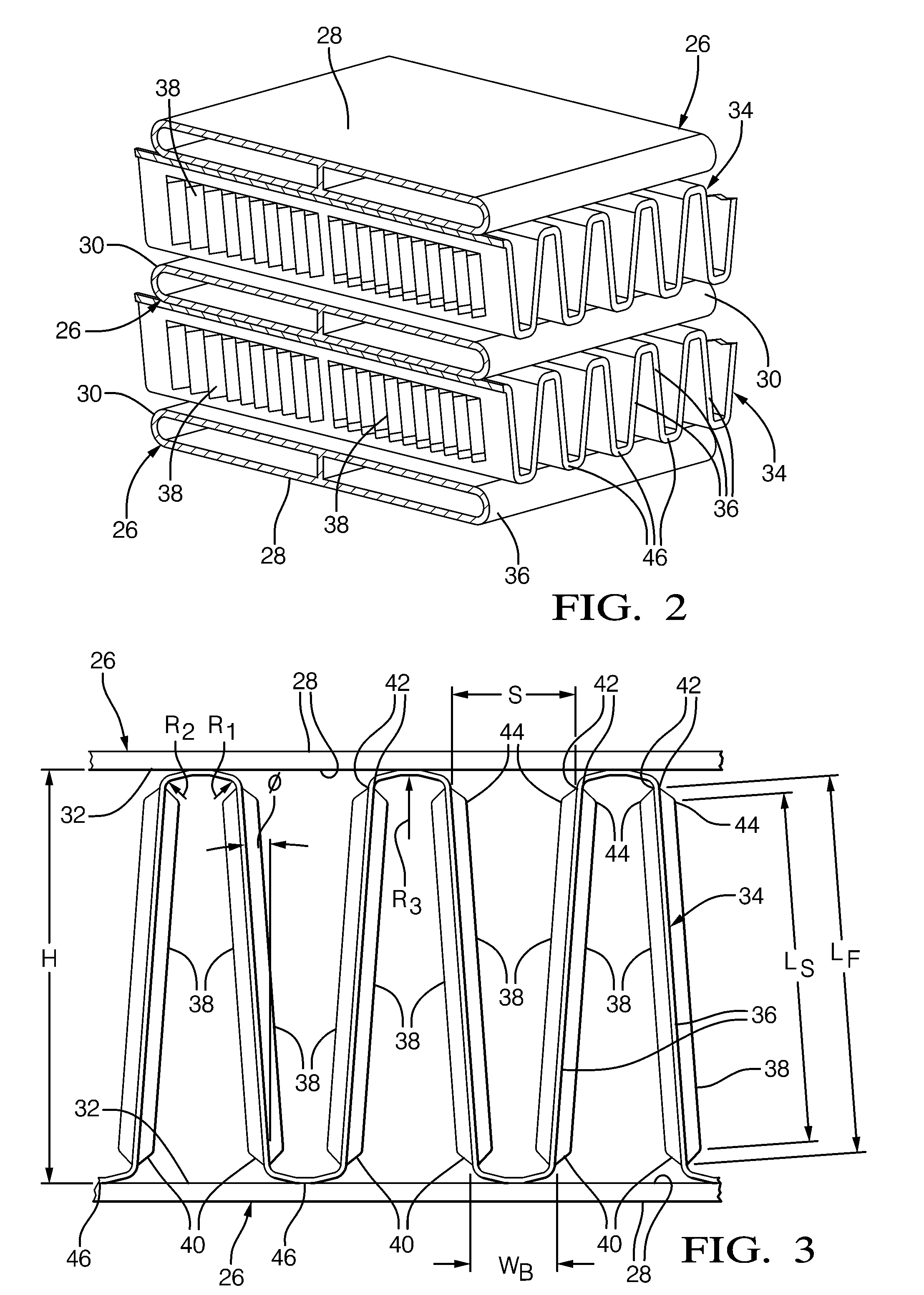
[0015]The assembly includes a first manifold 22 and a second manifold 24 in spaced and parallel relationship with one another. A plurality of tubes 26, generally indicated in FIGS. 2 and 3, extend in spaced and parallel relationship with one another between the first and second manifolds 22, 24 for conveying the coolant between the first and second manifolds 22, 24. Each of the tubes 26 has a cross-section presenting flat sides 28 extending in a transverse direction interconnected by round ends 30. The flat sides 28 of adjacent tubes 26 are spaced from one another by a fin space 32.

[0016]A plurality of air fi...


PUM


Abstract

A heat exchanger assembly including first and second manifolds for transferring heat between a coolant and a flow of air. Tubes extend between the manifolds for conveying the coolant therebetween. Air fins are disposed between adjacent tubes, and each air fin has a cross-section presenting a legs extending between the adjacent tubes at equal and opposing angles to one another and bases interconnecting alternate ends of the adjacent legs to present a serpentine pattern. Each base extends through an arc between the ends of the adjacent legs and defines a lead-in radius interconnecting each base with one of the legs and an exit radius interconnecting each base with the end of the adjacent leg. The equal and opposing angles are in the range of 1 to 4 degrees. The lead-in and exit radii are in the range of 0.05 to 0.15 mm. The middle radius is in the range of 0.5 to 1.5 mm.

Description

BACKGROUND OF THE INVENTION[0001]1. Field of the Invention[0002]A heat exchanger assembly for transferring heat between a coolant and a flow of air, and specifically to an improved air fin design.[0003]2. Description of the Prior Art[0004]Japanese Patent Application No. 10365226, issued to Hiroshi et al., shows a heat exchanger assembly for transferring heat between a coolant and a flow of air. The '388 application includes a first manifold and a second manifold, and a plurality of tubes extending in spaced and parallel relationship with one another between the first and second manifolds for conveying the coolant between the first and second manifolds. Adjacent tubes are spaced from one another by a fin space, and a plurality of air fins are disposed in the fin spaces. Each of the air fins has a cross-section presenting a plurality of legs and a plurality of bases interconnecting alternate ends of adjacent legs and engaging the adjacent tubes to present a serpentine pattern. Each of...

Claims


Application Information

Patent Timeline
IPC IPC(8): F28F1/24F28F9/02
CPCF28D1/0435F28F1/128F28D1/05383
Inventor LEITCH, FRANK J.COYLE, BRIAN J.MCDONALD, AARON D.FLICK, JACK B.PYANOWSKI, JOHN R.
Owner DELPHI TECH INC
Why Eureka
Try Eureka