Machine Tool Apparatus And Method

Active Publication Date: 2013-03-14
MAZAK CORP
View PDF6 Cites 20 Cited by
  • Summary
  • Abstract
  • Description
  • Claims
  • Application Information

AI Technical Summary

Benefits of technology

[0027]In one form, the cutting tool holder may be advanced toward the workpiece to machine the exterior of the workpiece with the cutting tool holder between the driven end and the supported end of the workpiece while the boring tool holder is located at

Problems solved by technology

When the boring tool is mounted to the cutting tool holder, the length of the boring tool

Method used


Image

  • Machine Tool Apparatus And Method
  • Machine Tool Apparatus And Method
  • Machine Tool Apparatus And Method

Examples


Embodiment Construction

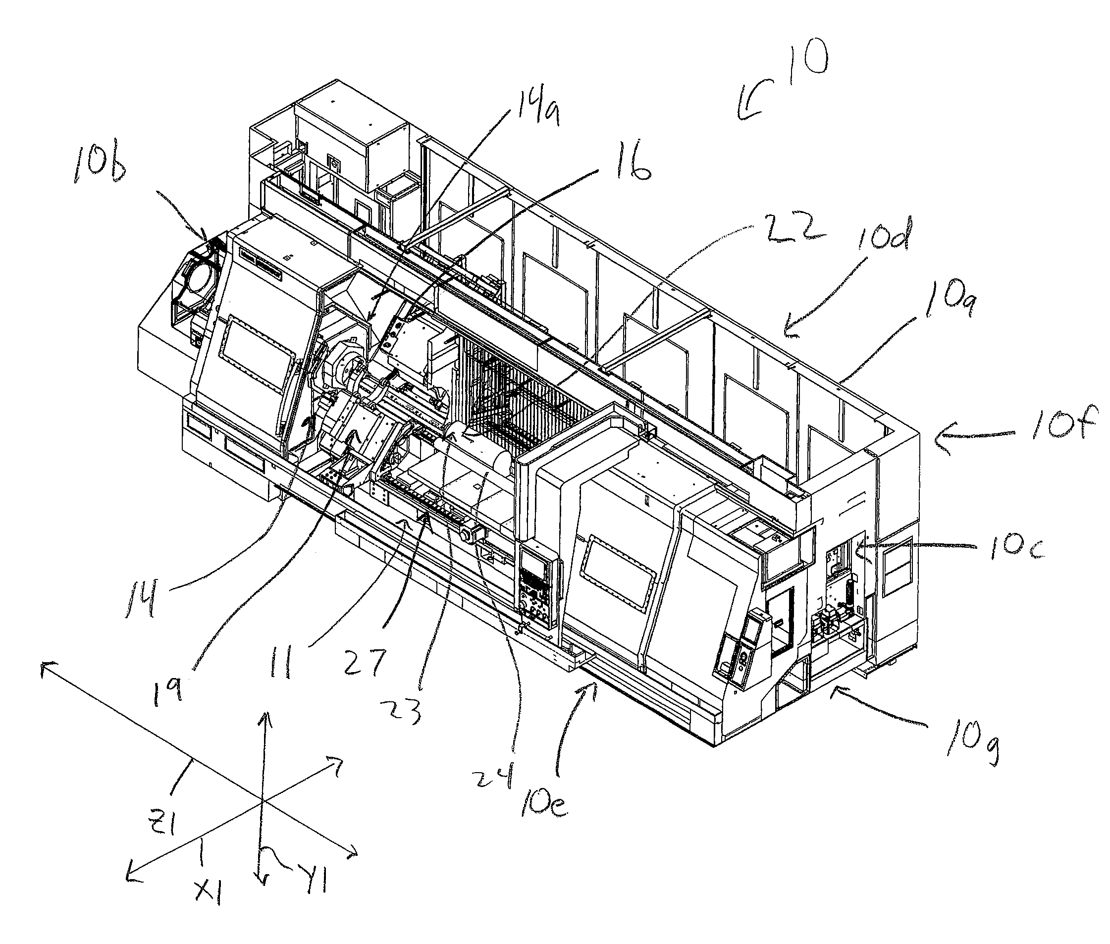
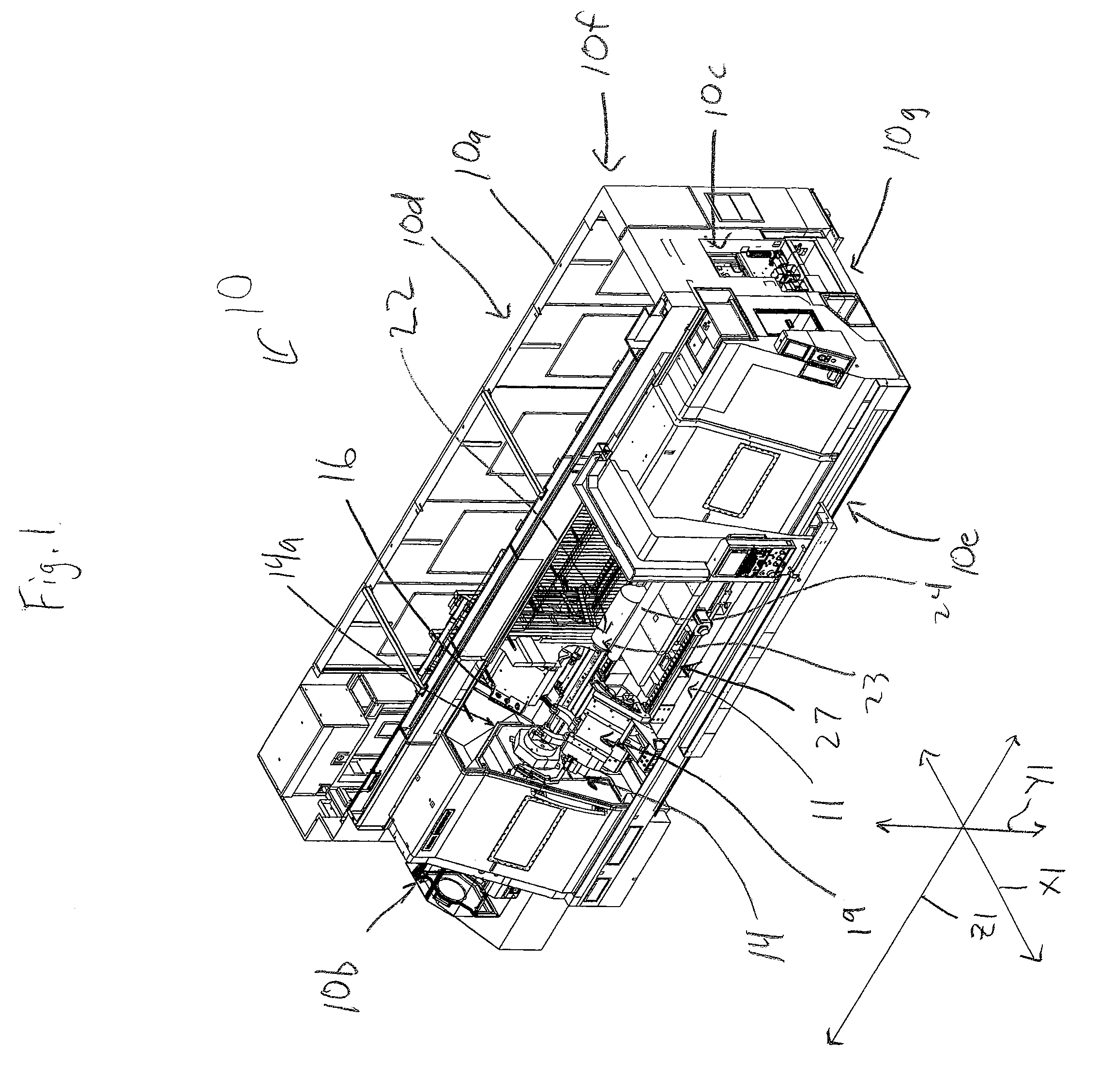
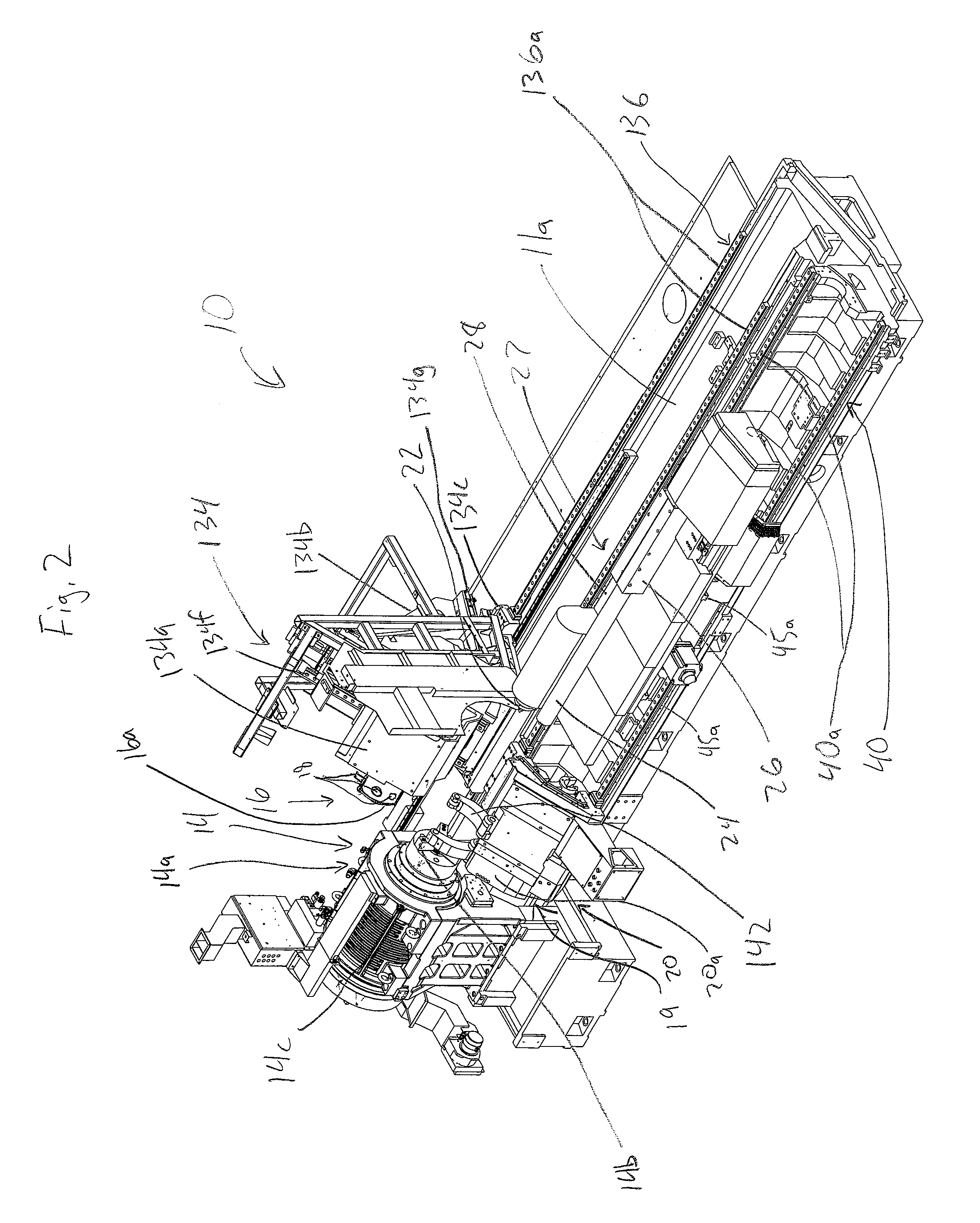
[0043]As shown, a turning center 10 is provided for machining a workpiece 12, such as a cylindrical bar or other elongated member. With reference to FIGS. 1-4, the turning center 10 generally includes a base 11, a work holder 14 in the form of the illustrated headstock 14a having a rotary drive 14c and chucking members 14b mounted thereto that are rotatably driven to rotate the workpiece 12, a cutting tool holder 16 in the form of the illustrated turret 16a holding multiple cutting tools 18 for machining the exterior of the workpiece 12, an intermediate work support 19 in the form of the illustrated steady rest 20 for engaging the exterior of the workpiece 12 and providing it support, an end work support 22 in the form of the illustrated tailstock 23 for engaging and supporting the end of the workpiece 12 opposite the work holder 14, a boring tool 24 for machining the interior of the workpiece 12, a boring tool holder 26 for holding the boring tool 24, and a common support assembly ...


PUM

PropertyMeasurementUnit
Lengthaaaaaaaaaa
Heightaaaaaaaaaa
Distanceaaaaaaaaaa

Abstract

A machine tool apparatus and method for exterior and interior cutting operations on a workpiece is provided. In one form, the machine tool apparatus has a common support assembly with a tailstock and a boring tool holder mounted thereto. The common support assembly has a common support carriage that is mounted to a machine base for travel along a longitudinal axis parallel to a central axis of the workpiece. The tailstock and boring tool holder are mounted to a mounting base portion for travel transverse to the workpiece central axis. In one form, a turret having external cutting tools is separate from the boring tool holder and mounted to the machine base for performing external cutting operations on the workpiece. This separate mounting allows the turret to machine the exterior of the workpiece while also permitting a longer boring tool to perform deep internal cutting operations on the workpiece.

Description

FIELD OF THE INVENTION[0001]The present invention relates to a machine tool apparatus and method and, more particularly, to a machine tool for exterior and interior cutting operations on a workpiece.BACKGROUND OF THE INVENTION[0002]Computer Numerical Control (CNC) machine tools are generally known in the art for use in machining various workpieces for a variety of uses. CNC tools commonly comprise a tooling center that secures the workpiece to be machined, as well as providing a plurality of tools for machining various internal and / or external features of the workpiece, as desired. The CNC tooling center machines the workpiece as directed by the computer, in response to computer aided design or computer aided manufacturing instructions.[0003]One type of CNC machine tool is a CNC turning center, such as the Mazak QTN450MY 3000U machine tool, provided by the applicants' assignee herein, Mazak Corporation. A CNC turning center generally includes a headstock, for securing one end of a w...

Claims


Application Information

Patent Timeline
IPC IPC(8): B23B23/00B23B29/24B23B21/00B23B3/22B23B1/00
CPCB23B23/00B23B3/06B23B5/08Y10T82/2564B23B29/04Y10T82/2508Y10T82/10B23B27/007
Inventor KATSU, YOSHIYAKAWAMURA, KOICHICOUCH, JIMMIEHADLEY, MARK
Owner MAZAK CORP
Why Eureka
Try Eureka