
Slot valve for use in the pneumatic switching circuit of a respirator

a technology of pneumatic switching and slot valve, which is applied in the direction of functional valve types, couplings, respirators, etc., can solve the problems of life-threatening shortness of breath, insufficient oxygen supply for the blood, and insufficient non-invasive respiration methods with merely increasing the oxygen concentration in the breathing air being supplied,

Active Publication Date: 2014-03-04
DRAGERWERK AG
View PDF24 Cites 10 Cited by
  • Summary
  • Abstract
  • Description
  • Claims
  • Application Information

AI Technical Summary

Benefits of technology

[0012]The object of the present invention is therefore to make available a valve for use in the pneumatic switching circuit of a respirator, by means of which the above-mentioned drawbacks are overcome. In particular, it is the object of the present invention to make available a valve for use in or at a tube (e.g., an endotracheal tube or a tracheotomy cannula) coupled with the respirator, by means of which a pressure drop in the lungs of a patient (especially of an ARDS patient) can be effectively prevented from occurring.
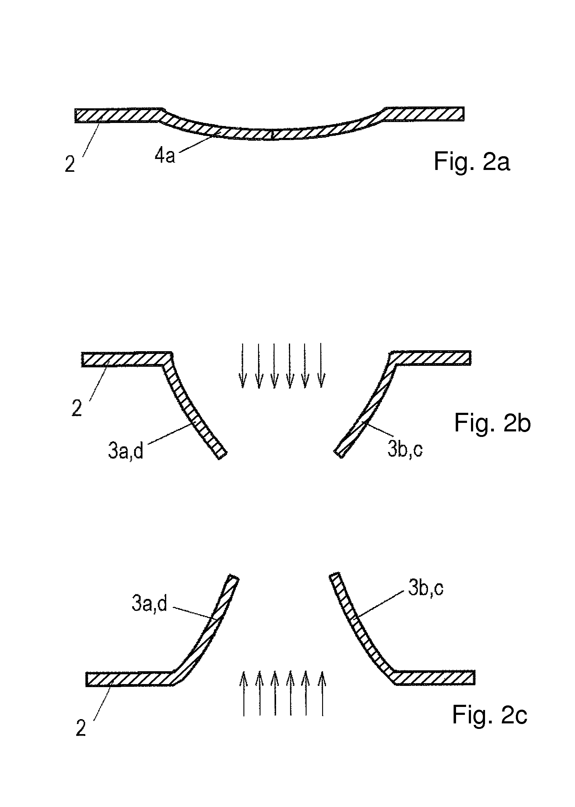
[0014]An essential advantage of the slot valve according to the present invention is that the valve acts bidirectionally and responds independently from the direction of flow or the direction of action of a fluid at different threshold pressures.
[0016]The slot valve according to the present invention is preferably used in the pneumatic switching circuit of a respirator and is consequently arranged in the flow path between the respirator and the patient to be respirated, especially an ARDS patient, who is preferably respirated in the PEEP mode. The pressure drop in the patient's lungs to below a predetermined pressure level of, for example, between about 5 and 15 mbar can be prevented from occurring by means of the slot valve according to the present invention during disconnection at the endotracheal tube or at the tracheotomy cannula (when, for example, the respirator is being replaced). Furthermore, the valve is designed to make inspiration possible without the patient having to generate a high suctioning pressure for this. The threshold value for opening the valve in the suction direction is therefore preferably below 5 mbar. The necessary threshold pressure to open the valve must be higher in the direction of expiration and equals more than 5 mbar, preferably more than 10 mbar or in exceptional cases more than 15 mbar, and these values may also vary in an especially advantageous embodiment depending on the patient to be respirated, depending on the intensity of the ARDS and depending on other factors. Furthermore, the valve is designed to make it possible to suction fluids from the lungs by means of a special cannula. The slot valve according to the present invention has a hygienic design, which permits use for more than 1 week. In a preferred embodiment the valve is designed in a special manner in order not to hinder the flow of breath during normal respiration. The slot valve according to the present invention is provided for this purpose with means that can be actuated manually in order to make a changeover between different modes of operation possible in a simple manner.
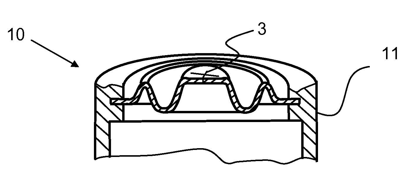
[0022]The valve according to the present invention may be designed, furthermore, as a “pop-up” valve. A depressible or foldable, annular intermediate area is provided for this between the inner, circular slot area and the outer supporting ring. This intermediate area is folded up or into one another in the closed resting state of the valve or in the state that prevails when the patient is breathing in and only a low threshold value (overpressure on the side of the respirator) is necessary for opening the membrane lamellae. When the patient is breathing out (overpressure on the patient side), the folded-up intermediate area is first unfolded. If the pressure rises further and exceeds said threshold value (e.g., 10 mbar or more), the membrane lamellae are folded over as well. It was found that the membrane lamellae are pressed better against each other when the intermediate area is folded up and overpressure prevails on the patient side. It is only when the intermediate area is unfolded that the transition section between the membrane lamellae and the intermediate area acquires the necessary flexibility to make it possible for the membrane lamellae to fold over easily when the patient-side pressure exceeds the predetermined threshold value during expiration. The foldable intermediate area thus acts as a kind of securing means against premature folding over of the membrane lamellae under the threshold pressure.
[0023]A releasing means, which folds the membrane lamellae out of the closed position on actuation, so that the flow channel in the interior of the valve is released, is additionally provided in another advantageous embodiment of the present invention. In a preferred embodiment of the slot valve according to the present invention, the valve is inserted into the breathing circuit between an endotracheal tube or a tracheotomy cannula on one side (patient side) and the filter, artificial nose, closed suction system or Y-piece on the other side (respirator side). The valve has a housing, a slot membrane with, for example, four or six radially extending slots, as a result of which cut membrane lamellae are formed, a rotary ring and a spreader. The spreader can be pushed into the range of action of the slot membrane such that the membrane lamellae of the slot membrane permanently release the flow center and do not represent a relevant flow resistance. The spreader has two oblique holding noses, which open through the housing into a groove of the rotary ring, which said groove is designed as an oblique path. The rotary ring additionally has an annular groove, into which snaps a bead of the housing. As a result, the rotary ring is fixed against axial displacement at the housing. When rotating the rotary ring, the spreader is displaced axially over the two oblique paths and can thus be brought optionally into a position close to the Y-piece, where the spreader does not mesh with the membrane and a pressure drop in the patient's lungs below, for example, 10 mbar is avoided. The spreader meshes with the membrane lamellae in the opposite position near the patient and pushes same out of the flow center, whereby unhindered, bidirectional flow of fluid through the valve is made possible.

Problems solved by technology

This leads to a life-threatening shortness of breath and to insufficient oxygen supply for the blood.
However, noninvasive respiration methods with merely increasing the oxygen concentration in the breathing air being supplied are often insufficient for the treatment of ARDS, because respirated ARDS patients have atelectatic (i.e., collapsed) lung areas, which can be opened (recruited) and made usable for gas exchange with a high respiration pressure only.
The necessary pressure in the lungs cannot be continuously maintained during the performance of these clinically necessary steps, so that the damaged lung areas must be recruited time and time again.
Changing of the device and changing of the closed suction system itself, which is necessary at 48-hour intervals for hygienic reasons, continue to lead to collapse of the lungs and to a subsequent stressful recruitment maneuver.
None of the above-mentioned documents pertains to the respiration of ARDS patients, and none of these documents discloses respirators or respirating means in the pneumatic switching circuit between a respirator and a patient, which are designed to maintain a certain air pressure in the lungs of the patient to be respirated even when, for example, the respirator is being replaced.

Method used


Image

  • Slot valve for use in the pneumatic switching circuit of a respirator
  • Slot valve for use in the pneumatic switching circuit of a respirator
  • Slot valve for use in the pneumatic switching circuit of a respirator

Examples


Embodiment Construction

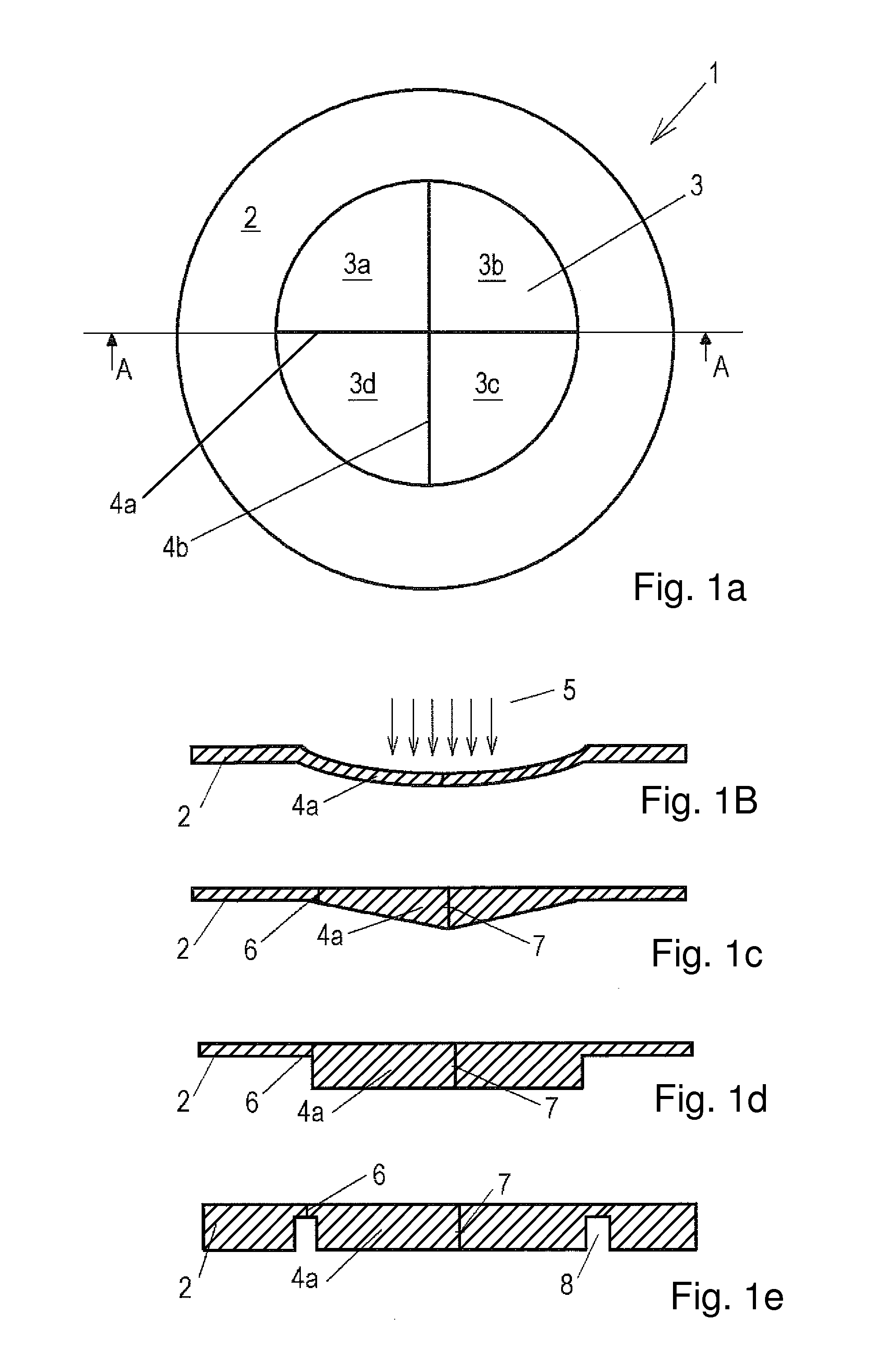
[0040]Referring to the drawings in particular, the figures will be described in detail below. FIG. 1a shows a top view of an exemplary slot membrane according to the present invention in its simplest embodiment. The slot membrane 1 has essentially the shape of a disk and is made of rubber, silicone rubber or a suitable elastic plastic material. The slot membrane 1 comprises a circular lamella area 3 with lamellae 3a through 3d, which are formed by slots 4a, 4b that intersect each other, and an annular supporting area 2, which surrounds the lamella area 3 and is used to fasten the slot membrane in a preferably annular valve housing. FIG. 1a shows two slots that intersect each other, as a result of which four circle segment-shaped lamellae are formed. However, it is also possible to provide three or more slots that intersect each other, as a result of which the total number of lamellae increases correspondingly.

[0041]FIG. 1b shows a cross-sectional view through line A-A from FIG. 1a, ...


PUM


Abstract

A slot valve (20) for use in the pneumatic switching circuit of a respirator, wherein said slot valve is designed to act bidirectionally and to pass over into the opened state to make possible the flow of a fluid at different pressure threshold values depending on the direction of flow of a fluid.

Description

CROSS REFERENCE TO RELATED APPLICATIONS[0001]This application claims the benefit of priority under 35 U.S.C. §119 of European Patent Application EP 09 158 904.4 filed Apr. 28, 2009, the entire contents of which are incorporated herein by reference.FIELD OF THE INVENTION[0002]The invention relates to a slot valve for use in the pneumatic switching circuit of a respirator (also known as ventilator) and more particularly to a valve connected at a tube (e.g., an endotracheal tube or a tracheotomy cannula) coupled with the respirator.BACKGROUND OF THE INVENTION[0003]ARDS (acute respiratory deficiency syndrome) designates a sudden respiratory failure, which develops due to an acute inflammatory process of the lung tissue, in which the lungs extensively lose their ability to exchange gas. The permeability of the blood vessels in the pulmonary alveoli increases in ARDS and the pressure in the vessels drops, whereas it rises in other parts of the lung tissue. This leads to a life-threatening...

Claims


Application Information

Patent Timeline
Patent Type & Authority Patents(United States)
IPC IPC(8): F16K17/26
CPCA61M16/20A61M2016/206Y10T137/7895Y10T137/7885A61M16/206Y10T137/7771A61M16/0833F16K15/144
Inventor HANSMANN, HANS-ULRICHKOULECHOV, KIRLLVON BLUMENTHAL, TILMANHENGSTENBERG, ANDREASNEUMANN, ANDREASWALL, TORGEOTTO, ANDREASKAEMER, MARKUS
Owner DRAGERWERK AG
Learn More