A body structure of AT power roll-core autotransformer

A technology of autotransformer and rolled iron core, which is applied in the direction of transformer/inductor core, transformer, fixed transformer, etc., to achieve the effect of strengthening insulation performance and heat dissipation performance, and reducing loss value

Inactive Publication Date: 2015-04-22
WOLONG ELECTRIC GRP CO LTD +1
View PDF6 Cites 5 Cited by
  • Summary
  • Abstract
  • Description
  • Claims
  • Application Information

AI Technical Summary

Problems solved by technology

Conventional autotransformer body structure is difficult to meet the requirements of electrified railway due to design limitations, insulation strength, overload capacity, short-circuit resistance capacity and high loss.

Method used


Image

  • A body structure of AT power roll-core autotransformer
  • A body structure of AT power roll-core autotransformer
  • A body structure of AT power roll-core autotransformer

Examples


Embodiment Construction

[0015] The technical solution of the present invention will be further described in detail below in conjunction with the accompanying drawings.

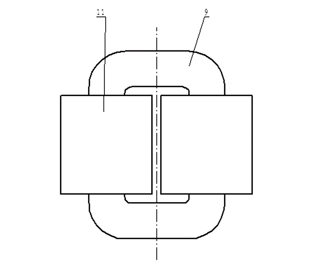
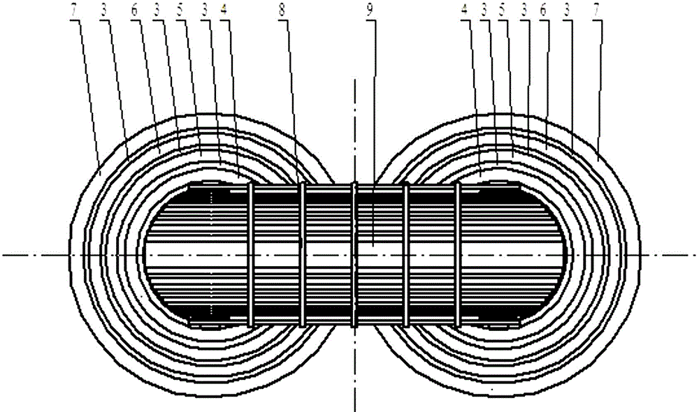
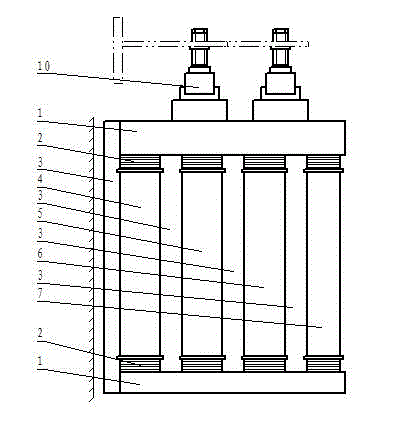
[0016] Such as figure 1 , 2 , 3, the present invention includes an iron core 9, a coil, an insulator 3 and a pressing device, the iron core 9 is a single-frame closed winding core structure, the vertical column of the iron core 9 is an iron core column, and the horizontal direction of the iron core 9 The column is an iron yoke, and a plurality of concentric coils are wound on one iron core column. The upper and lower ends of each coil are provided with insulating end rings 2, and the lower end of the lower insulating end ring 2 and the upper end of the upper insulating end ring 2 are provided with Iron yoke insulation board1. The iron core 9 is a closed structural iron core 9 with a circular or elliptical cross section rolled from a silicon steel sheet.

[0017] In order to strengthen the integrity of the iron core, the iron core ...


PUM


Abstract

A body structure of an AT power roll-core autotransformer relates to a body of a transformer. Insulation strength, an overload ability, an anti-short circuit ability, a high loss, etc. of a conventional autotransformer body structure cannot meet requirements of an electric railway. An iron core of the body structure of the AT power roll-core autotransformer is a single frame closed roll core structure, vertical columns of the iron core are iron core columns, and horizontal columns of the iron core are iron yokes. A plurality of concentric coils are wound around each iron core column, and upper and lower ends of each coil are both provided with insulation end rings. A lower end of a lower insulation end ring and an upper end of an upper insulation end ring are both provided with iron yoke insulation plates. Pressing devices are disposed on the upper iron yoke insulation plate, and integrally press the coil, the insulation end ring, and the iron core as a whole. The present technical solution uses the body structure of the roll-core autotransformer to enhance the insulation property and heat dispersion property, to improve the overload ability and the anti-short circuit ability of the transformer, to reduce the loss value of the transformer, and to meet the special requirements of the electric railway.

Description

technical field [0001] The invention relates to a transformer body. Background technique [0002] With the continuous development of electrified railways, especially the rapid development of high-speed and heavy-duty railways, the AT power supply method has been recognized and affirmed, and the AT power supply autotransformer has developed rapidly. In order to meet the requirements of high overload, frequent short circuit, low impedance and low loss of fast railway traction lines. Conventional autotransformer body structure is difficult to meet the requirements of electrified railway due to design limitations, insulation strength, overload capacity, short-circuit resistance and high loss. Contents of the invention [0003] The technical problem to be solved and the technical task proposed by the present invention are to perfect and improve the existing technical solutions, and to provide an AT power supply wound core autotransformer body structure, so as to improve the in...

Claims


Application Information

Patent Timeline
Patent Type & Authority Applications(China)
IPC IPC(8): H01F30/02H01F27/26H01F27/25H01F27/30
Inventor 马金山鲁玮张健王娥胡保国
Owner WOLONG ELECTRIC GRP CO LTD
Why Eureka
Try Eureka