Al technical title is built by PatSnap Al team. It summarizes the technical point description of the patent document.
A soap and rotating rack technology, used in the field of household appliances, can solve problems such as breaking
Active Publication Date: 2019-11-01
ANHUI HEBANG TEXTILE TECH CO LTD
View PDF11 Cites 0 Cited by
Summary
Abstract
Description
Claims
Application Information
AI Technical Summary
This helps you quickly interpret patents by identifying the three key elements:
Problems solved by technology
Method used
Benefits of technology
Problems solved by technology
Soap will be broken at the end, so it is a pity to throw it away. In order to use these broken soaps, a broken soap recycling device is designed
Method used
Image
Click on the blue label to locate the original text in one second.
Reading with bidirectional positioning of images and text.
Examples
specific Embodiment approach 1
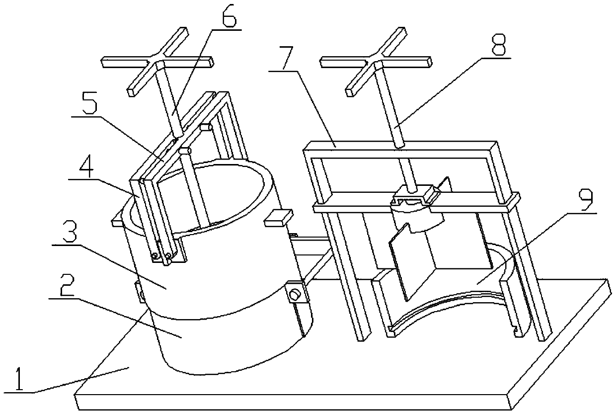
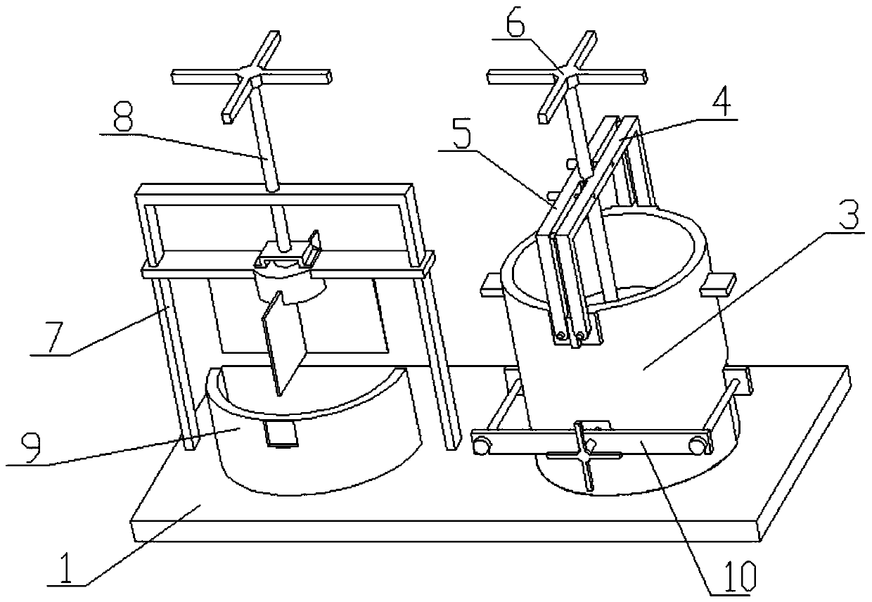
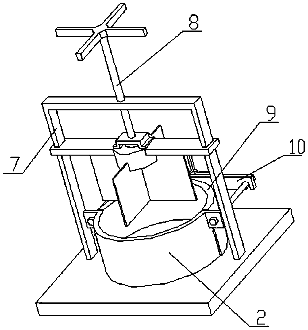
[0047] Combine below Figure 1-24 To illustrate this embodiment, the present invention relates to a living appliance, more specifically a broken soap recycling device, including a bottom plate 1, a soap base 2, a pressing cylinder 3, a rotating frame I4, a rotating frame II5, a pressing Device 6, screw hole plate 7, cutting device 8, cutting cylinder 9 and soap base fastening device 10, the device can compact and cut the leftover broken soap to achieve the effect of waste reuse.
[0048] The soap bottom bracket 2 includes an arc side baffle 2-1, a baffle I 2-2, an ear plate 2-3, a stretch bar 2-4, a baffle II 2-5, a circular bottom bracket 2-6, a convex Circle 2-7, card rib 2-8, pressure ring 2-9 and card rib groove 2-10, the cross section of arc side baffle 2-1 is semicircle, the lower end of arc side baffle 2-1 A circular bottom support 2-6 is welded, and a convex circle 2-7 is welded in the middle of the circular bottom support 2-6, and a card edge 2-8 is symmetrically wel...
specific Embodiment approach 2
[0060] Combine below Figure 1-24 This embodiment will be described, and this embodiment will further describe Embodiment 1. The threaded hole III 7 - 1 is coaxial with the cutting cylinder 9 .
[0061] Specific implementation mode two:
[0062] Combine below Figure 1-24 This embodiment will be described. This embodiment will further describe the first embodiment. The length of the spacer 4-2 is equal to the width of the middle rib 3-5.
[0063] The working principle of a broken soap recycling device of the present invention: the rotating frame I4 and the rotating frame II5 are usually placed on the rotating frame placing plate 3-3, and when the crushed soap is pressed, the pressing ring 2-9 is removed, and the Place the net cloth on the circle 2-7, install the pressure ring 2-9 on the convex circle 2-7, and insert the card edge groove 2-10 quasi-card edge 2-8 on the pressure ring 2-9 into the convex circle 2 -7, then stagger the card edge 2-8 and the card edge groove 2-10...
PUM
Abstract
The invention relates to articles for life, in particular to a broken soap reuse device. By means of the device, remaining broken soap can be compacted and diced to achieve the waste reuse effect. When the device is in a soap compacting state, a pressing cylinder is connected to a bottom plate in a welded mode, a soap bottom support is inserted to a soap bottom supporting groove, a round bottom support is inserted into a round bottom support insertion groove I, two stretching rods are inserted into two stretching rod insertion grooves, a screw III abuts against a screw top groove I, a rotary frame I and a second rotary frame II are connected to two rotary frame connection bases through pins respectively, a pressing plate on the pressing device is inserted in the pressing cylinder, the rotary frame I and the second rotary frame II are fixed together through two hand screws, and a screw I is matched with a threaded sleeve I and a threaded sleeve II through threads. When the device is in a soap cutting state, a dicing cylinder is connected to the bottom plate in a welded mode, and two supporting rods on a screw porous plate are connected to the bottom plate in a welded mode.
Description
technical field [0001] The invention relates to a living utensil, in particular to a broken soap recycling device. Background technique [0002] Soap is a general term for fatty acid metal salts. The general formula is RCOOM, where RCOO is a fatty acid radical, and M is a metal ion. The carbon number of fatty acids in daily-use soaps is generally 10-18, and the metals are mainly alkali metals such as sodium or potassium. There are also special-purpose soaps made of ammonia and some organic bases such as ethanolamine and triethanolamine. In a broad sense, fatty acid salts obtained from saponification or neutralization reactions of grease, wax, rosin or fatty acids with alkalis can all be called soaps. Soap is soluble in water and has the effect of washing and decontamination. There are various types of soaps such as toilet soap, metal soap and complex soap. Fatty acid salts of other metals, which are insoluble or difficult to dissolve in water, and have no cleaning effect...
Claims
Application Information
Patent Timeline
Application Date:The date an application was filed.
Publication Date:The date a patent or application was officially published.
First Publication Date:The earliest publication date of a patent with the same application number.
Issue Date:Publication date of the patent grant document.
PCT Entry Date:The Entry date of PCT National Phase.
Estimated Expiry Date:The statutory expiry date of a patent right according to the Patent Law, and it is the longest term of protection that the patent right can achieve without the termination of the patent right due to other reasons(Term extension factor has been taken into account ).
Invalid Date:Actual expiry date is based on effective date or publication date of legal transaction data of invalid patent.