Motor braking device

A technology of brake devices and brake pads, which is applied in the direction of electromechanical devices, electrical components, electric components, etc., and can solve problems such as inability to release the brakes

Active Publication Date: 2017-07-21
SHENZHEN JINGZHI HI TECH ROBOT CO LTD
View PDF5 Cites 3 Cited by
  • Summary
  • Abstract
  • Description
  • Claims
  • Application Information

AI Technical Summary

Problems solved by technology

[0002] The motor brake is to install an electromagnetic brake at the tail of the motor. When the motor is energized, the electromagnet attracts the armature block, and the armature block is separated from the brake pad. At this time, the armature block does not brake the motor. When the motor is powered off, the armature block The block is in a tight state with the brake pad under the action of the spring, and the armature block brakes the motor; when the motor is in the braking state, it must be energized when the motor shaft needs to be rotated, so the existing motor brake device cannot be released when the power is off. verb: move

Method used


Image

  • Motor braking device
  • Motor braking device
  • Motor braking device

Examples


Embodiment Construction

[0017] It should be noted that, in the case of no conflict, the embodiments in the present application and the features in the embodiments can be combined with each other. The present invention will be further described below in conjunction with the accompanying drawings.

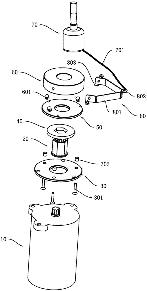
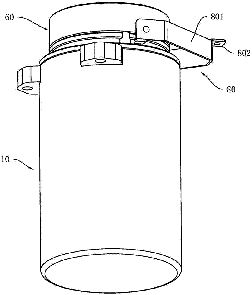
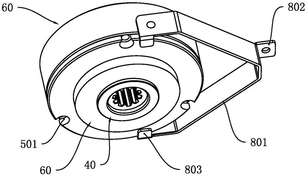
[0018] Such as Figure 1 to Figure 4 As shown, a motor braking device includes a motor 10, a shaft coupling 20 around the main shaft of the motor 10, and the coupling 20 is sequentially covered with a bottom plate 30, a brake pad 40, and an armature block 50 from the direction close to the motor 10 to the direction away from the motor 10. and the electromagnet 60; and the brake pad 40 is interference fit with the coupling 20, the base plate 30, the armature block 50 and the electromagnet 60 are respectively in clearance fit with the coupling 20; the base plate 30 and the electromagnet 60 pass through the connecting rod 301 provided Fixed connection, the armature block 50 slides freely along the connecting ...


PUM


Abstract

The invention discloses a motor braking device. The motor braking device includes a motor, a coupling that sleeves a spindle of a motor, and the coupling is sleeved by a bottom plate, a brake pad, an armature block and an electromagnet in sequence in a direction from close to the motor to away from the motor; the brake pad is in interference fit with the coupling, and the bottom plate, the armature block and the electromagnet are in clearance fit with the coupling; the bottom plate and the electromagnet are fixedly connected through an arranged connecting rod, the armature block slides freely along the connecting rod, and a spring is arranged between the armature block and the electromagnet; the motor braking device also includes a braking pull rod, a braking pressing piece, a stay wire and a sensor; and the braking pressing piece includes a pressing piece main body, a first pressing piece and a second pressing piece. The advantages are that under the circumstance of a power failure, the stay wire drives the breaking pressing piece to rotate, the second pressing piece presses the armature block towards the direction of the electromagnet, at the moment the armature block and the brake block are in a loosened state, and the motor braking device releases braking; and the sensor can measure the variation of the length of the stay wire, and can accurately calculate the braking force.

Description

technical field [0001] The invention relates to a motor braking device. Background technique [0002] The motor brake is to install an electromagnetic brake at the tail of the motor. When the motor is energized, the electromagnet attracts the armature block, and the armature block is separated from the brake pad. At this time, the armature block does not brake the motor. When the motor is powered off, the armature block The block is in a tight state with the brake pad under the action of the spring, and the armature block brakes the motor; when the motor is in the braking state, it must be energized when the motor shaft needs to be rotated, so the existing motor brake device cannot be released when the power is off. move. Contents of the invention [0003] The purpose of the present invention is to solve the deficiencies of the prior art and provide a motor braking device. [0004] A kind of technical scheme of the present invention: [0005] A motor braking device, com...

Claims


Application Information

Patent Timeline
Patent Type & Authority Applications(China)
IPC IPC(8): H02K7/102
CPCH02K7/1023
Inventor 冷哲陈超彭银华
Owner SHENZHEN JINGZHI HI TECH ROBOT CO LTD
Why Eureka
Try Eureka