Eureka AIR delivers breakthrough ideas for toughest innovation challenges, trusted by R&D personnel around the world.

Punching device for antenna reflecting surface

A punching device and reflective surface technology, applied in punching tools, metal processing equipment, manufacturing tools, etc., can solve the problems of difficulty in punching inclined holes and complicated processes

Active Publication Date: 2017-07-25
TONGYU COMM INC
View PDF7 Cites 1 Cited by
  • Summary
  • Abstract
  • Description
  • Claims
  • Application Information

AI Technical Summary

Problems solved by technology

[0003] The invention provides a punching device for the antenna reflective surface to solve the problems in the prior art that the oblique hole punching is difficult and the process is complicated

Method used


Image

  • Punching device for antenna reflecting surface

Examples


Embodiment Construction

[0016] In order to enable those skilled in the art to better understand the technical solution of the present invention, the punching device for the antenna reflective surface of the present invention will be further described in detail below in conjunction with the accompanying drawings and specific embodiments.

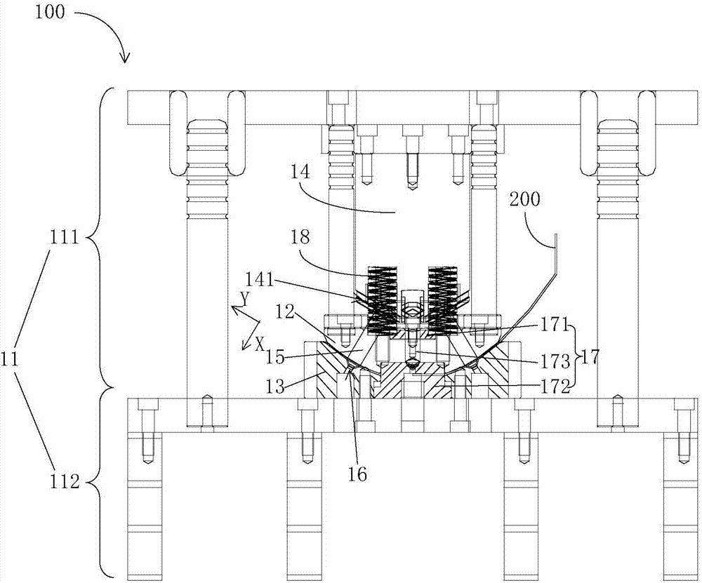
[0017] see figure 1 , figure 1 It is a structural diagram of an embodiment of the punching device for the antenna reflector of the present invention. The punching device 100 in this embodiment includes a bracket 11 , a punch 12 and a die 13 , a slider 14 and a punch 15 .

[0018] Wherein, described die 13 is arranged on the bottom 112 of support 11, and punch 12 is arranged on the top 111 of support 11 with respect to die 13, and the upper part 111 of support 11 and the lower part 112 are set movably, can be adjusted up and down, when pairing antenna When the reflective surface 200 is punched, the antenna reflective surface 200 can be installed between the male mol...


PUM

PropertyMeasurementUnit
diameteraaaaaaaaaa

Abstract

The invention discloses a punching device for an antenna reflecting surface. The punching device comprises a support, a male die, a female die, a sliding block and punching pins. The female die is arranged on the lower portion of the support. The male die is arranged on the upper portion of the support relative to the female die. The upper portion and the lower portion of the support are movably arranged so that the antenna reflecting surface can be fixed between the male die and the female die. The protruded surface of the male die, the recessed surface of the female die and the antenna reflecting surface have the same hook face shape. The punching pins are arranged on oblique grooves of the sliding block, and the length direction of the punching pins is perpendicular to the antenna reflecting surface. The sliding block can be driven by power to move up and down between the upper portion and the lower portion of the support, and thus the punching pins can be pushed to be stretched out and drawn back in the length direction of the punching pins. The male die and the female die are provided with corresponding through holes, and the punching pins penetrate through the corresponding through holes. The antenna reflecting surface can be punched when the punching pins are stretched out and drawn back. According to the punching device for the antenna reflecting surface, oblique holes can be punched for the antenna reflecting surface accurately and efficiently.

Description

technical field [0001] The invention relates to the field of manufacturing machinery of communication equipment, in particular to a punching device for an antenna reflection surface. Background technique [0002] When the antenna reflector is in use, it is usually connected to other devices, so it is necessary to punch oblique installation holes on the curved surface of the antenna reflector. In the prior art, limited by the diameter and slope of the antenna reflection surface, punching is difficult, and only a single hole can be punched. When there are many mounting holes, multiple operations are required and the process is complicated. Contents of the invention [0003] The invention provides a punching device for an antenna reflection surface to solve the problems in the prior art that punching inclined holes is difficult and the process is complicated. [0004] In order to solve the above-mentioned technical problems, the present invention provides a punching device f...

Claims


Application Information

Patent Timeline
Patent Type & Authority Applications(China)
IPC IPC(8): B21D28/32B21D28/34
CPCB21D28/32B21D28/34
Inventor 窦华土李莹光吴中林粟炳龙刘华宝张君陈鹏羽
Owner TONGYU COMM INC
Why Eureka
Eureka Blog
Learn More