Eureka AIR delivers breakthrough ideas for toughest innovation challenges, trusted by R&D personnel around the world.

Electric control cabinet L-shaped steel member punching device

A punching device and a technology for steel components, applied in the field of L-shaped steel component punching devices for electric control cabinets, can solve problems such as low precision and low punching efficiency, increase efficiency and reduce the time for multiple punching , the effect of easy support

Inactive Publication Date: 2019-10-22
安徽蓝润正华电子有限公司
View PDF7 Cites 4 Cited by
  • Summary
  • Abstract
  • Description
  • Claims
  • Application Information

AI Technical Summary

Problems solved by technology

[0006] The purpose of the present invention is to overcome the deficiencies of the prior art and to meet the needs of the reality. It provides a punching device for L-shaped steel components for electric control cabinets, so as to solve the problem that the traditional L-shaped steel components need to be punched by processing personnel first. Measure, determine the hole position, and then perform a single punch on the determined position. The punching efficiency is low and the accuracy is not high.

Method used


Image

  • Electric control cabinet L-shaped steel member punching device
  • Electric control cabinet L-shaped steel member punching device
  • Electric control cabinet L-shaped steel member punching device

Examples


Embodiment Construction

[0026] Attached below Figure 1-5 The present invention is further described with embodiment:

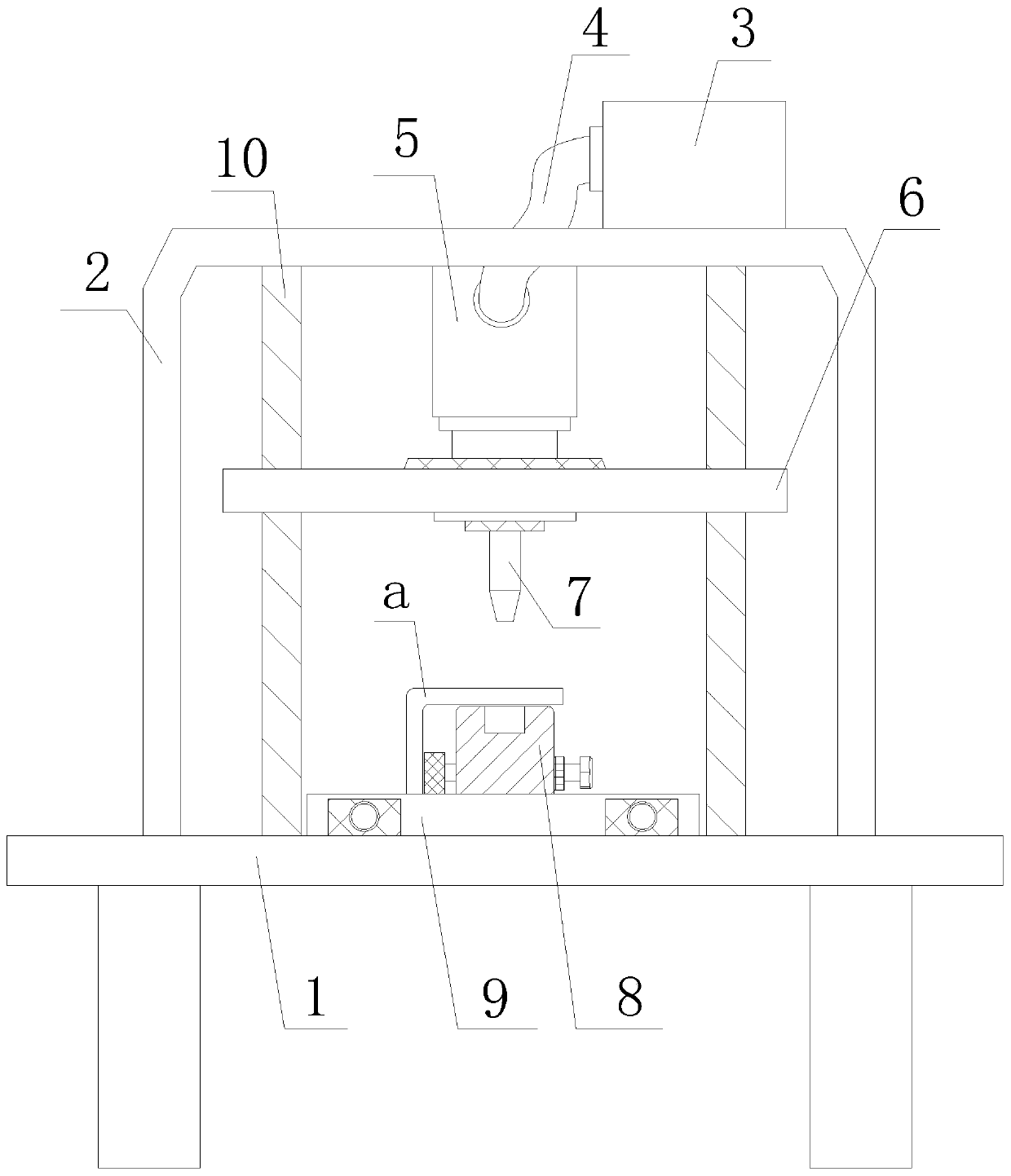
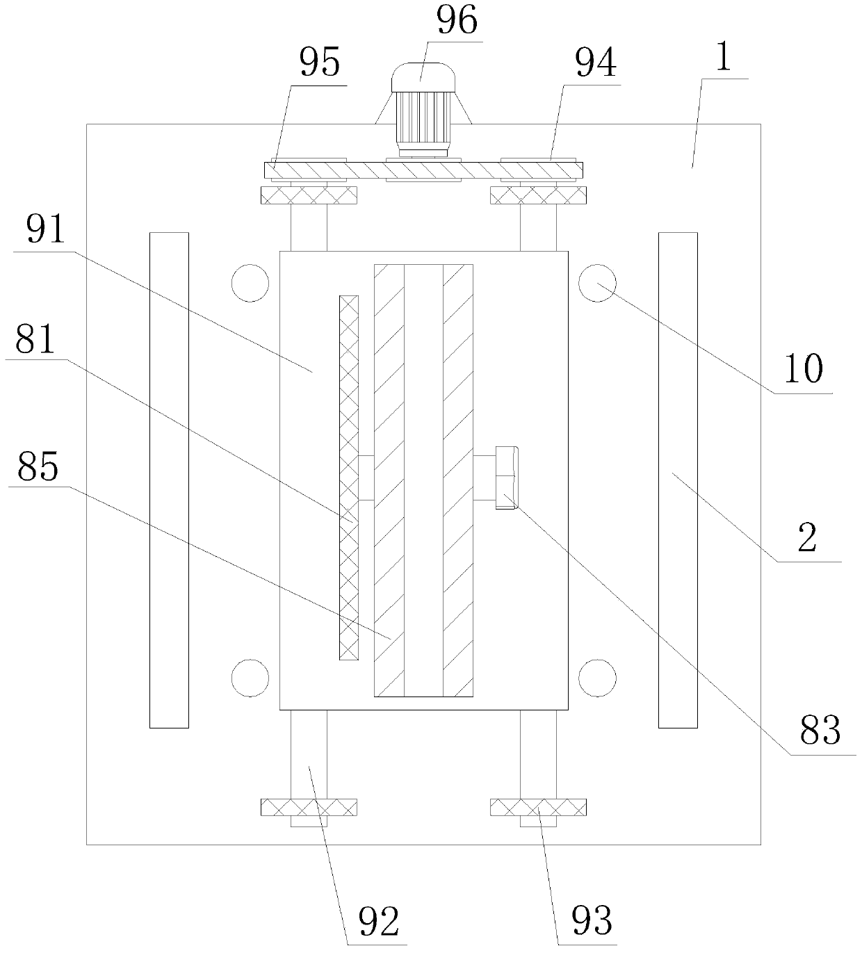
[0027] A punching device for an L-shaped steel member for an electric control cabinet, comprising a processing table 1, a plurality of supporting feet installed at the lower end of the processing table 1, and a frame 2 provided at the upper end of the processing table 1, the three form a stable whole, and the effective To ensure the installation of the punching device, a hydraulic station 3 is installed on the upper end of the frame 2, and the output end of the hydraulic station 3 is connected with two hydraulic rods 5 through the infusion tube 4, and the hydraulic rods 5 are fixedly installed on the machine. On the inner top wall of the frame 2, the same lifting plate 6 is installed on the output ends of the two hydraulic rods 5, and the lower end of the lifting plate 6 is detachably installed with a plurality of parallel punching heads 7 through the fixing seat. , the hydraulic s...


PUM


Abstract

The invention relates to the technical field of electric control cabinet machining equipment and provides an electric control cabinet L-shaped steel member punching device, so that the problems that when a traditional L-shaped steel member is punched, machining personnel need to measure first to determine the hole positions, then the determined positions are punched one by one, the punching efficiency is low, and the precision is low are solved. The device comprises a machining table and a rack arranged at the upper end of the machining table. A hydraulic pressure station is mounted at the upper end of the rack, and the output end of the hydraulic pressure station is connected with two hydraulic rods through liquid conveying tubes in a penetrating mode. The hydraulic rods are fixedly mounted on the inner top wall of the rack, and a same lifting plate is mounted at the output ends of the two hydraulic rods. A plurality of parallel punching heads are detachably mounted at the lower end of the lifting plate through fixing seats correspondingly. An adjustable supporting device is arranged under the multiple punching heads. The electric control cabinet L-shaped steel member punching device is particularly suitable for electric control cabinet interior L-shaped stele member efficient and precise punching, the social application value is high, and the application prospects are good.

Description

technical field [0001] The invention relates to the technical field of electric control cabinet processing equipment, in particular to a punching device for an L-shaped steel member used in an electric control cabinet. Background technique [0002] Electric control cabinet is to assemble switchgear, measuring instrument, protective device and auxiliary equipment in closed or semiclosed metal cabinet or on screen width according to electrical wiring requirements, and its layout should meet the requirements of normal operation of power system, and is easy to overhaul and does not endanger people. Safety control cabinet (box) for personal and surrounding equipment. [0003] The processing of existing electric control cabinets needs to use metal plates for welding and assembly, and when the metal plates are assembled into electric control cabinets, L-shaped steel components need to be used for assembly and fixing. At this time, the L-shaped steel components need to be Punch hol...

Claims


Application Information

Patent Timeline
Patent Type & Authority Applications(China)
IPC IPC(8): B21D28/24
CPCB21D28/24
Inventor 庄连美陈万林秦喜春
Owner 安徽蓝润正华电子有限公司
Why Eureka
Eureka Blog
Learn More