
Logging machine delimbing device
A technology of logging machine and mechanical arm, which is applied in the field of logging machine components, can solve the problems of large blade wear, affecting logging efficiency, and the trunk cannot continue to drive, so as to improve the service life and stability of use, and prevent the reaction force from being damaged. clear efficient effect
- Summary
- Abstract
- Description
- Claims
- Application Information
AI Technical Summary
Problems solved by technology
Method used
Image

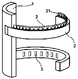
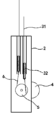
Examples
Embodiment
[0015] exist figure 1 , figure 2 In the shown embodiment, the delimbing device of the logging machine includes a base plate 1 and a mechanical arm 2, the mechanical arm 2 is pivotally connected to the base plate 1, and the movement of the mechanical arm 2 is controlled by a driving motor;
[0016] The mechanical arm 2 is arc-shaped, and a cutting knife group is arranged in the mechanical arm 2. The cutting knife group includes two groups of parallel knife rows 3, and each row of knife rows 3 includes a knife seat 32 and a blade 31. Blade 31 stretches out from the upper surface of mechanical arm 2; figure 1 Shown; Each row of knife rows 3 can reciprocate and translate in the plane where the blade 31 is located; the blade 31 is made of a permanent magnetic material, and the magnetic heteropoles of each row of blades 31 attract each other;
[0017] The inner ring arm of described mechanical arm 2 is provided with driving roller 4, and driving roller 4 can rotate freely around ...
PUM
 Abstract
Description
Claims
Application Information