
Feller delimbing device

A technology of a feller and a robotic arm, applied in the field of feller components, can solve the problems of large blade wear, affecting the logging efficiency, and the trunk cannot continue to drive, so as to improve the service life and use stability, and prevent the reaction force from being damaged. Clear Efficient Effects

Active Publication Date: 2017-08-04
常熟后土科技发展有限公司
View PDF6 Cites 6 Cited by
  • Summary
  • Abstract
  • Description
  • Claims
  • Application Information

AI Technical Summary

Problems solved by technology

[0002] At present, with the continuous increase of labor costs, the felling of large quantities of trees in forest farms, farms and municipalities can no longer rely solely on manpower. Special logging machines have been developed to replace manpower. , measuring, and cutting a series of actions; an important device in the logging machine is convenient for the branch cleaning device. During the trunk cutting process, the branches need to be trimmed and cleaned to ensure that the trunk is clean and tidy; the traditional branch cleaning device includes a blade structure, In the process of trunk transmission, the blade is used for vertical impact cutting. For small branches, this method is competent. When faced with thicker branches, the blade cannot cut off the branch, the transmission device is suspended, and the trunk cannot continue to drive. Affect the subsequent cutting operation of the trunk; in addition, this way of handling the branches will cause greater wear and tear on the blade, and at the same time, the single-layer blade is easy to get stuck between the wood layers and cannot be pulled out. Once the blade is stuck, the blade will lose the momentum of cutting. At this time, the logging machine is stuck and cannot move forward or backward, which seriously affects the logging efficiency

Method used


Image

  • Feller delimbing device
  • Feller delimbing device

Examples


Embodiment

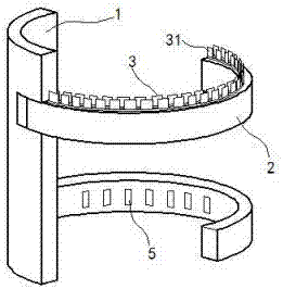
[0015] exist figure 1 , figure 2 In the shown embodiment, the delimbing device of the logging machine includes a base plate 1 and a mechanical arm 2, the mechanical arm 2 is pivotally connected to the base plate 1, and the movement of the mechanical arm 2 is controlled by a driving motor;

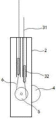
[0016] The mechanical arm 2 is arc-shaped, and a cutting knife group is arranged in the mechanical arm 2. The cutting knife group includes two groups of parallel knife rows 3, and each row of knife rows 3 includes a knife seat 32 and a blade 31. Blade 31 stretches out from the upper surface of mechanical arm 2; figure 1 Shown; Each row of knife rows 3 can reciprocate and translate in the plane where the blade 31 is located; the blade 31 is made of a permanent magnetic material, and the magnetic heteropoles of each row of blades 31 attract each other;

[0017] The inner ring arm of described mechanical arm 2 is provided with driving roller 4, and driving roller 4 can rotate freely around ...


PUM


Abstract

The invention relates to a feller delimbing device comprising a base plate and mechanical arms. The mechanical arms are connected on the base plate through shafts; the mechanical arms are controlled to move through a driving motor and are in arc shapes; a cutting knife set is arranged in each mechanical arm and comprises two parallel knife columns; each knife column comprises a knife seat and blades, and the blades stretch out of the upper surfaces of the mechanical arms; each knife column can translate in a reciprocating mode in the face where the blades are located; a driving roller is arranged on the inner annular wall of each mechanical arm and can rotate freely around the axis of the driving roller; the outer wheel face of each driving roller is exposed out from the inner annular wall of the corresponding mechanical arm; each driving roller is engaged with a set of cutting wheels through transmission wheels; transmission rods are installed on the wheel edges of the cutting wheels in a hinged mode; and the tail ends of the transmission rods are hinged to knife seats. The feller delimbing device is novel and unique in structure and capable of removing a limb in flat and smooth modes, blade clamping is effectively prevented, and working efficiency is improved.

Description

technical field [0001] The present invention relates to a feller assembly and, in particular, to a delimbing device. Background technique [0002] At present, with the continuous increase of labor costs, the felling of large quantities of trees in forest farms, farms and municipalities can no longer rely solely on manpower. Special logging machines have been developed to replace manpower. , measuring, and cutting a series of actions; an important device in the logging machine is convenient for the branch cleaning device. During the trunk cutting process, the branches need to be trimmed and cleaned to ensure that the trunk is clean and tidy; the traditional branch cleaning device includes a blade structure, In the process of trunk transmission, the blade is used for vertical impact cutting. For small branches, this method is competent. When faced with thicker branches, the blade cannot cut off the branch, the transmission device is suspended, and the trunk cannot continue t...

Claims


Application Information

Patent Timeline
IPC IPC(8): B27L1/00
CPCB27L1/005
Inventor 钱月珍
Owner 常熟后土科技发展有限公司
Learn More