A segmented turbine blade for a hydraulic torque converter

A technology of hydraulic torque converter and turbine blades, which is applied in the direction of instruments, belts/chains/gears, transmission devices, etc., can solve the problems of poor flow conditions at the turbine inlet, low transmission efficiency, and large oil flow loss, etc., to achieve Eliminate ultra-high vortex, improve transmission efficiency, and improve the effect of force on blades

Active Publication Date: 2021-02-02
JILIN UNIV
View PDF11 Cites 0 Cited by
  • Summary
  • Abstract
  • Description
  • Claims
  • Application Information

AI Technical Summary

Problems solved by technology

[0005] 2. There is an obvious vortex formation at the inlet of the pressure surface of the turbine blade, the flow condition at the turbine inlet is poor, and the transmission efficiency is low
[0006] 3. The oil flow loss in the maximum curvature section of the blade is huge

Method used


Image

  • A segmented turbine blade for a hydraulic torque converter
  • A segmented turbine blade for a hydraulic torque converter
  • A segmented turbine blade for a hydraulic torque converter

Examples


Embodiment 1

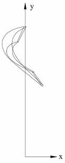
[0073] The main vane 2 and the tail vane 3 of the designed torque converter turbine blade of embodiment 1 are arranged on top (as Figure 3b-2 shown). According to the three-dimensional model of the turbine blade in the embodiment, the bone line and blade shape of the blade are extracted, the blade shape and bone line of the original blade, and the blade shape and bone line obtained by segmentation processing in Embodiment 1 of the present invention are as follows: Figure 4a~4d shown. Figure 4a~4d In the spatial coordinate system of , the rotation axis of the torque converter is the z axis, the xoy plane is the interface between the pump wheel and the turbine, and the direction where the turbine points to the pump wheel is the positive direction of the z axis. Extract the three-dimensional bone line coordinates of the blade, and use MATLAB to process the data points of the blade bone line to obtain the expression of the blade bone line in the space coordinate system. Among...

Embodiment 2

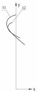
[0093] The main blade 2 and tail blade 4 of the designed torque converter turbine blade of the embodiment of the present invention 2 are arranged in a staggered manner (as Figure 3c-2 shown). According to the three-dimensional model of the turbine blade established in embodiment 2, the blade bone line and blade shape are extracted, and the blade blade shape and blade shape obtained by segmental processing in embodiment 1 of the invention are Figure 4e and Figure 4f shown. Extract the three-dimensional bone line coordinates of the blade, and use MATLAB to process the data points of the blade bone line to obtain the expression of the blade bone line in the space coordinate system. The expression of the bone line of its main blade in the space coordinate system is consistent with embodiment 1, and the expression of the outer ring bone line 41 of the tail blade in the space coordinate system is

[0094]

[0095] The expression of the inner ring bone line 42 of the tail bl...

Embodiment 3

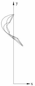
[0099]The main vane 2 and the tail vane 5 of the designed torque converter turbine blade of the embodiment of the present invention 3 are in overlapping arrangement (as Figure 3d-2 shown). According to the three-dimensional model of the turbine blade established in embodiment 3, the blade bone line and blade shape are extracted, and the blade blade shape and bone line obtained by segmentation processing in embodiment 3 of the present invention are as follows: Figure 4g and Figure 4h shown. Extract the three-dimensional bone line coordinates of the blade, and use MATLAB to process the data points of the blade bone line to obtain the expression of the blade bone line in the space coordinate system. The expression of the bone line of its main blade in the space coordinate system is consistent with embodiment 1, and the expression of the outer ring bone line 51 of the tail blade in the space coordinate system is

[0100]

[0101] The expression of the inner ring bone line...


PUM


Abstract

The invention relates to a segmented turbine blade of a hydraulic torque converter. The turbine blade is segmented in a position with a pressure value of 0 on a pressure surface; the blade near a turbine inlet part is a main blade; the blade near a turbine outlet is a tail blade; the main blade near the position with the pressure value of 0 on the pressure surface is a transition section; the transition section is formed by flatly shifting an original pressure surface to a suction surface by 2 / 5-3 / 5 of the blade thickness; and the position with the pressure value of 0 on the pressure surface is connected in an arc manner. The turbine blade is segmented on the edge of a high-pressure area of the pressure surface of the turbine blade; the turbine blade of the hydraulic torque converter is designed as two segments; the area transited from the main blade to the segmented place is formed by flatly shifting the original pressure surface to the suction surface by 2 / 5-3 / 5 of the blade thickness; and the position with the pressure value of 0 on the pressure surface is connected in an arc manner, so that the pressure of the pressure surface of a turbine can be increased, the torque of the turbine is increased, the torque conversion ratio is increased, and the purpose of improving the efficiency of the torque converter is achieved.

Description

technical field [0001] The invention belongs to the technical field of hydraulic transmission, and in particular relates to a segmented turbine blade of a hydraulic torque converter. Background technique [0002] Torque converter is an impeller machine that relies on fluid kinetic energy to transmit power. It has the advantages of load self-adaptation, stepless speed change, vibration reduction and vibration isolation, and stable low-speed performance. It is widely used in military industry, petroleum machinery, automobiles, construction machinery, agricultural Machinery, construction machinery and other industries. As a transmission device, the hydraulic torque converter has lower transmission efficiency than mechanical transmission systems such as gear transmission, which not only limits the application range of the hydraulic torque converter, but also causes waste of resources and energy and more Emissions lead to environmental degradation. [0003] The existing hydraul...

Claims


Application Information

Patent Timeline
Patent Type & Authority Patents(China)
IPC IPC(8): F16H41/26G06F30/17G06F30/28G06T17/00G06F111/10
CPCF16H41/26G06F30/17G06F2119/06G06F2119/18
Inventor 刘春宝李静徐志轩
Owner JILIN UNIV
Why Eureka
Try Eureka