Eureka AIR delivers breakthrough ideas for toughest innovation challenges, trusted by R&D personnel around the world.

An intelligent pumping unit operating condition test device

A testing device and pumping unit technology, which is applied to measuring devices, testing of machine/structural components, instruments, etc., can solve the problems of not being able to test the load of the wire rope in the whole process, not being able to enter the oil pipe, and not being able to test the displacement at the same time.

Inactive Publication Date: 2017-08-22
西安康际石油科技有限公司
View PDF8 Cites 0 Cited by
  • Summary
  • Abstract
  • Description
  • Claims
  • Application Information

AI Technical Summary

Problems solved by technology

[0002] The traditional three-point test wire rope load requires the tested wire rope to pass through the test device after unloading, and load the load after installation. Only the static load can be tested and the displacement cannot be tested at the same time. The test device and the tested steel wire rope are fixed and relatively static. The movement of the steel wire rope will drive the test device together. sports
The load wire rope of the intelligent pumping unit passes through the oil pipe and moves back and forth in the oil pipe for a long distance, so it cannot be unloaded during the test. The traditional test device needs to move together with the wire rope due to limitations, and cannot enter the oil pipe, resulting in the inability to test the wire rope load throughout the process.

Method used


Image

  • An intelligent pumping unit operating condition test device
  • An intelligent pumping unit operating condition test device
  • An intelligent pumping unit operating condition test device

Examples


Embodiment Construction

[0013] In order to make the object, technical solution and advantages of the present invention clearer, the present invention will be further described in detail below in conjunction with the accompanying drawings.

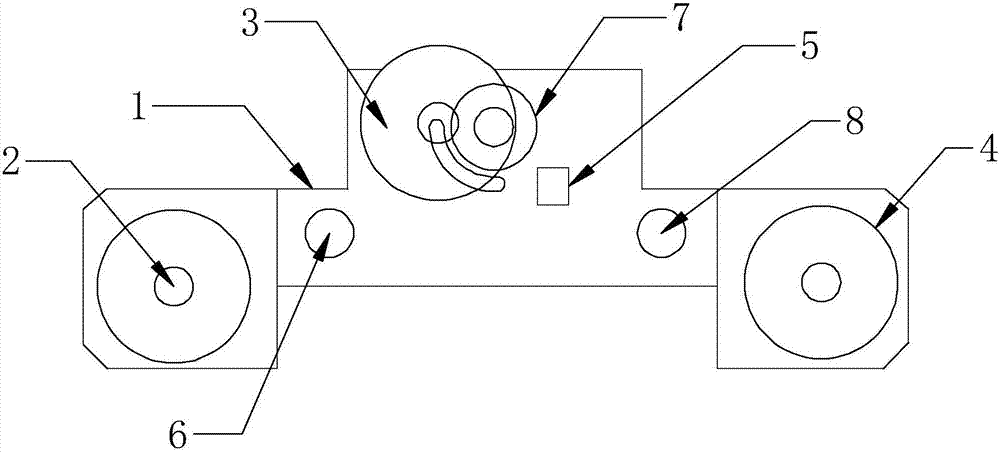
[0014] The working condition test device of the intelligent pumping unit in the embodiment of the present invention, in figure 1 Among them, the fixed shaft pulley 2, the deflection pulley 3, and the counting pulley 4 are fixed on the body 1 in a triangular distribution, and the deflection pulley 3 can rotate 90 degrees around the deflection axis 7, and thrust against the thrust block 5 when it deflects downward. Test The front deflection pulley 3 deflects 90 degrees upwards, so that the wire rope passes through without unloading. The strain gauges 6 are symmetrically distributed on the sensor body and are used to calculate the load.

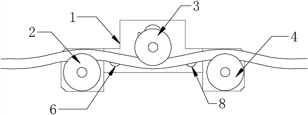
[0015] exist figure 2 In the shown embodiment, the test device is in the test state, the deflection pulley 3 deflects downward ...


PUM


Abstract

The embodiment of the present invention discloses an intelligent oil pumping unit working condition testing device. The intelligent oil pumping unit working condition testing device is characterized in that it comprises a main body, fixed shaft pulleys and counting pulleys respectively connected to the two ends of the main body. , the upper part of the body is also connected with a deflection pulley through the deflection shaft, the deflection pulley rotates along the chute located at the lower left side of the deflection shaft, and the deflection pulley slides down to the bottom position, and a thrust block is provided, A strain gauge is also arranged between the fixed shaft pulley in the middle of the body and the counting pulley; an encoder is also connected to the counting shaft of the counting pulley. It is an intelligent pumping unit working condition testing device that is in contact with the wire rope through a pulley and moves relative to it, and is suitable for the whole process of testing the wire rope movement.

Description

technical field [0001] The invention relates to the field of testing devices, in particular to an intelligent pumping unit working condition testing device. Background technique [0002] The traditional three-point test wire rope load requires the tested wire rope to pass through the test device after unloading, and load the load after installation. Only the static load can be tested and the displacement cannot be tested at the same time. The test device and the tested steel wire rope are fixed and relatively static. The movement of the steel wire rope will drive the test device together. sports. The load wire rope of the intelligent pumping unit passes through the oil pipe and moves back and forth in the oil pipe for a long distance, so it cannot be unloaded during the test. The traditional test device needs to move with the wire rope due to limitations and cannot enter the oil pipe, resulting in the inability to test the wire rope load throughout the process. Contents of...

Claims


Application Information

Patent Timeline
IPC IPC(8): G01M99/00
CPCG01M99/005
Inventor 马刚娃
Owner 西安康际石油科技有限公司
Why Eureka
Eureka Blog
Learn More