Compression cycle system

A compression cycle and compressor technology, applied in the field of compressors, can solve problems such as high power consumption, inapplicability of one-way circulation system, and high noise

Pending Publication Date: 2017-08-29
GREE ELECTRIC APPLIANCES INC
View PDF9 Cites 1 Cited by
  • Summary
  • Abstract
  • Description
  • Claims
  • Application Information

AI Technical Summary

Problems solved by technology

Among them, the four-way valve reversing reverse cycle defrosting method is mature, but the noise is relatively large, and it is not suitable for the one-way cycle system
The energy of hot gas bypass defrosting only comes from the input power of the compressor, and the defrosting effect is poor
The electric heating defrosting method generally consumes a lot of power.

Method used


Image

  • Compression cycle system
  • Compression cycle system
  • Compression cycle system

Examples


Embodiment Construction

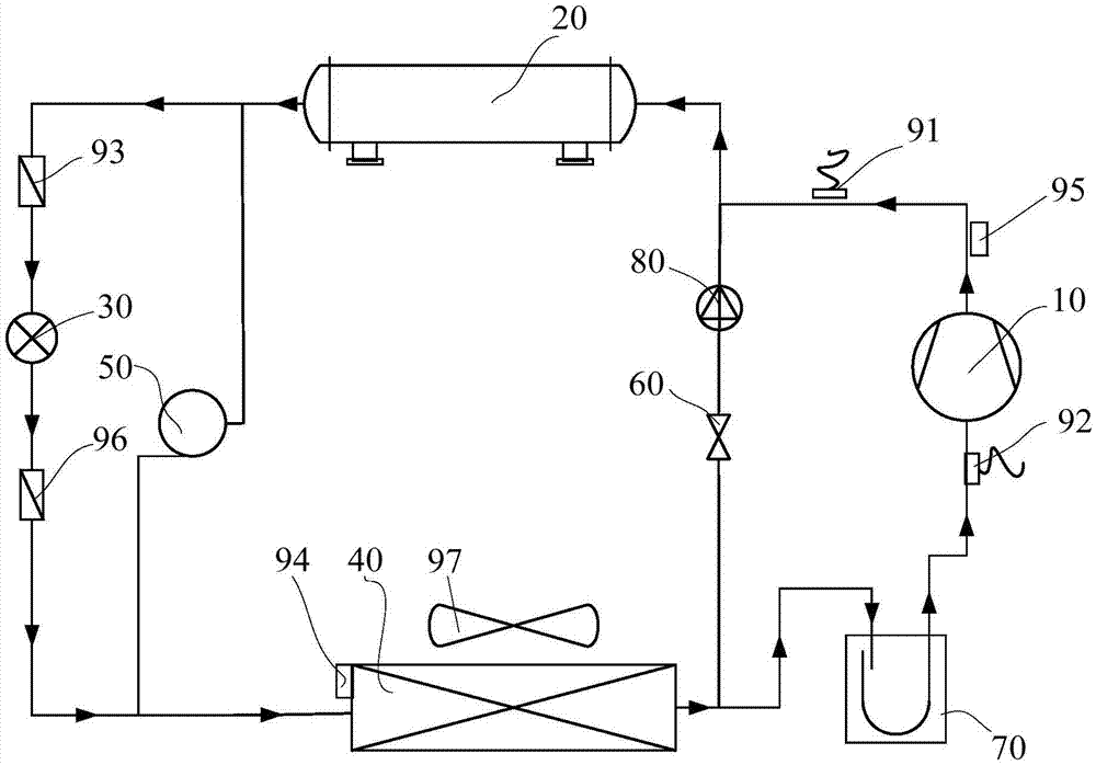
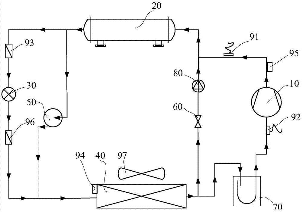
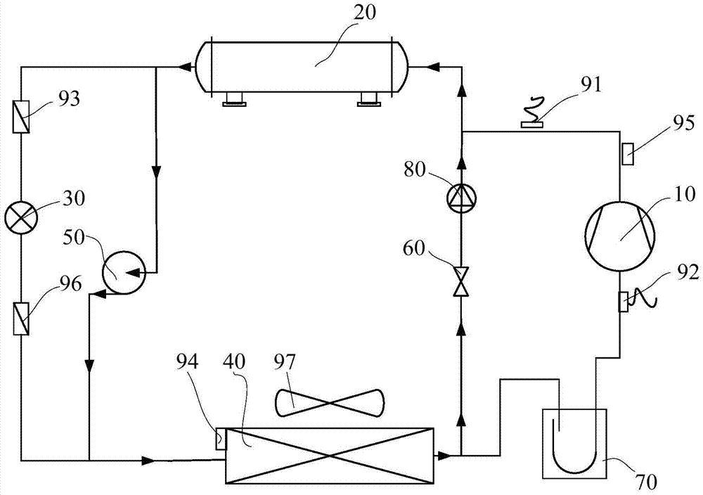
[0022] The present invention will be described in detail below with reference to the accompanying drawings and examples.

[0023] Such as figure 1 As shown, the compression cycle system according to the present invention includes a compression cycle loop, and the compression cycle loop includes a compressor 10, a first heat exchanger 20, a second heat exchanger 40, and a first throttling device 30 arranged in series, and the compression cycle system Also includes a defrosting circuit, the defrosting circuit includes: a refrigerant pump 50, the first end of the refrigerant pump 50 is connected to the first end of the first heat exchanger 20, the second end of the refrigerant pump 50 is connected to the second end of the second heat exchanger 40 The second end is connected; the second throttling device 60, the first end of the second throttling device 60 is connected with the first end of the second heat exchanger 40, the second end of the second throttling device 60 is connecte...


PUM


Abstract

The invention provides a compression cycle system which comprises a compression cycle loop. The compression cycle loop comprises a compressor, a first heat exchanger, a second heat exchanger and a first throttling device which are serially connected. The compression cycle system also comprises a defrosting loop. The defrosting loop comprises a refrigerant pump and a second throttling device; the first end of the refrigerant pump is connected with the first end of the first heat exchanger; the second end of the refrigerant pump is connected with the second end of the second heat exchanger; the first end of the second throttling device is connected with the first end of the second heat exchanger; and the second end of the second throttling device is connected with the second end of the first heat exchanger. According to the compression cycle system provided by the invention, the defrosting loop is arranged in the compression cycle system, the refrigerant pump in the defrosting loop drives a high-temperature refrigerant in the first heat exchanger to the second heat exchanger, the high-temperature refrigerant is throttled to the compression cycle loop through the second throttling device so as to be cycled continuously, and the second heat exchanger is heat by the high-temperature refrigerant, so that a defrosting function is realized.

Description

technical field [0001] The invention relates to the technical field of compressors, in particular to a compression cycle system. Background technique [0002] In a low temperature environment, when the surface temperature of the outdoor heat exchanger in the heat pump system is lower than the air dew point, the water vapor in the air is very easy to condense a frost layer on the surface of the outdoor heat exchanger, resulting in a greatly reduced heat transfer efficiency of the fin heat exchanger , the expected effect cannot be achieved, so it is necessary to defrost the outdoor heat exchanger. [0003] The existing defrosting methods are mainly four-way valve reversing reverse cycle defrosting, hot gas bypass defrosting, electric heating defrosting and so on. Among them, the four-way valve reversing reverse cycle defrosting method is mature, but the noise is relatively large, and it is not suitable for the one-way cycle system. The energy of hot gas bypass defrosting onl...

Claims


Application Information

Patent Timeline
Patent Type & Authority Applications(China)
IPC IPC(8): F25B1/00F25B47/02
CPCF25B1/00F25B47/02F25B2400/0401F25B2600/02F25B2700/21152F25B2700/21
Inventor 张恩泉刘华陈培生卓明胜王传华孙思吴呈松郑伟平林海东魏峰
Owner GREE ELECTRIC APPLIANCES INC
Why Eureka
Try Eureka