Reflector device for road

A reflective mirror and road technology, applied in the field of road reflective mirrors, can solve the problems of increased difficulty of road reflective mirrors, cumbersome and laborious operation process, inconvenient adjustment and installation, etc., and achieve the effects of reducing equipment complexity, increasing installation speed, and simple structure

Active Publication Date: 2019-09-27
山东誉滕医疗器械有限公司
View PDF4 Cites 0 Cited by
  • Summary
  • Abstract
  • Description
  • Claims
  • Application Information

AI Technical Summary

Problems solved by technology

[0002] Road reflectors are widely used in road construction, and are generally installed on winding roads or places with sharp turns, so that drivers can observe the road conditions on the opposite curved road before turning and improve driving safety. However, road reflectors are installed and fixed. It is necessary to adjust the orientation and angle accordingly. The orientation and angle adjustment of traditional road reflectors are all done manually. The operation process is cumbersome and laborious, and the installation efficiency is low. At the same time, road maintenance or route changes When the road reflector needs to be adjusted twice, it will be more difficult, which will bring inconvenience to the adjustment and installation

Method used


Image

  • Reflector device for road
  • Reflector device for road
  • Reflector device for road

Examples


Embodiment Construction

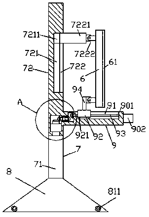
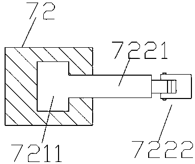
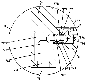
[0018] Such as Figure 1-Figure 4 As shown, a road reflector device of the present invention includes a vertical rod 7 connected by an upper straight rod 72 and a lower straight rod 71 and a control part 9 fixedly connected to the upper straight rod 72. The inner bottom of the rod 72 is provided with a transfer groove 723, and the upper end of the lower straight rod 71 is fixed with a transfer shaft 711, and the upper end of the transfer shaft 711 penetrates the bottom end surface of the upper straight rod 72, and the transfer The upper end of the shaft 711 penetrates into the transfer groove 723, the upper end of the transfer shaft 711 is fixedly provided with a jacking block 712, the upper end of the jacking block 712 is provided with a first toothed disc 714, and the control part 9 is fixedly arranged On the upper straight rod 72 outside the right side of the transfer groove 723, a second sliding connection groove 91 is arranged in the upper end of the control part 9, and a...


PUM


Abstract

The invention discloses a reflective mirror device for road. The device comprises an upright which is formed in the mode that an upper straight bar is connected with a lower straight bar and a manipulation portion which is fixedly connected with the upper straight bar, a transferring groove is formed in the bottom of the upper straight bar, and a transferring shaft is fixedly arranged at the upper end of the lower straight bar; the upper end of the transferring shaft penetrates through the bottom of the upper straight bar and enters the transferring groove, a top block is fixedly arranged at the upper end of the transferring shaft, and a first toothed dish is arranged at the upper end of the top block; the manipulation portion is fixedly arranged on the upper straight bar outside the right side of the transferring groove, a second sliding groove is formed in the upper end of the manipulation portion, and a second sliding block and a second heliciform rod are arranged in the second sliding groove; the second sliding block is connected with the second heliciform rod in a threaded and matched mode, idler wheels are arranged on the bottom of the second sliding block, and the idler wheels are connected with the bottom face of the second sliding groove in a rolling and matched mode; a first sliding cavity is formed in the manipulation portion of the left side of the second sliding groove, a second sliding cavity is formed between the bottom of the left side of the first sliding cavity and the upper end of the right side of the transferring groove, and a second toothed dish which penetrates though the wall body of the manipulation portion and enters the first sliding cavity is arranged on the left side of the second heliciform rod and rotatably connected with the second heliciform rod in a matched mode.

Description

technical field [0001] The invention relates to the technical field of road reflectors, in particular to a road reflector device. Background technique [0002] Road reflectors are widely used in road construction, and are generally installed on winding roads or places with sharp turns, so that drivers can observe the road conditions on the opposite curved road before turning and improve driving safety. However, road reflectors are installed and fixed. It is necessary to adjust the orientation and angle accordingly. The orientation and angle adjustment of traditional road reflectors are all done manually. The operation process is cumbersome and laborious, and the installation efficiency is low. At the same time, road maintenance or route changes When the road reflector needs to be adjusted twice, the difficulty increases, which brings inconvenience to the adjustment and installation. Contents of the invention [0003] The technical problem to be solved by the present inven...

Claims


Application Information

Patent Timeline
Patent Type & Authority Patents(China)
IPC IPC(8): E01F9/619E01F9/65
Inventor 沈奇
Owner 山东誉滕医疗器械有限公司
Why Eureka
Try Eureka