A led street lamp with high solar energy utilization rate

A technology of LED street lamps and utilization rate, which is applied in the directions of energy-saving lighting, components of lighting devices, semiconductor devices of light-emitting elements, etc. The effect of conversion utilization, reduction of equipment complexity, and convenient operation

Active Publication Date: 2018-03-02
江苏鹏华照明集团有限公司
View PDF5 Cites 0 Cited by
  • Summary
  • Abstract
  • Description
  • Claims
  • Application Information

AI Technical Summary

Problems solved by technology

Solar street lights must use solar cell components to provide electrical energy. For different regions and seasons, the installation inclination and azimuth of solar cell components are different. Traditional solar LED street lights have a single fixing method and complex structures. The adjustment angle is limited, so Can not get sufficient lighting effect, so it can not fully perform photoelectric conversion, resulting in low conversion utilization rate of solar energy

Method used


Image

  • A led street lamp with high solar energy utilization rate
  • A led street lamp with high solar energy utilization rate
  • A led street lamp with high solar energy utilization rate

Examples


Embodiment Construction

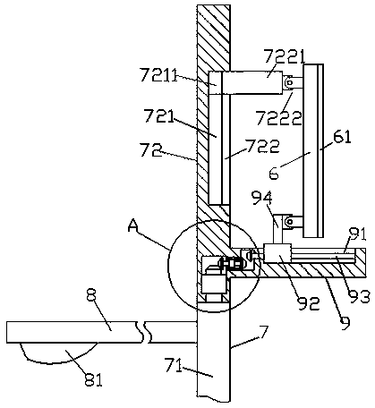
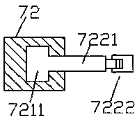
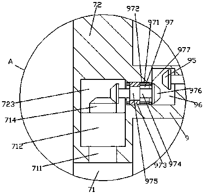
[0018] Such as Figure 1-Figure 4 As shown, a LED street lamp with high solar energy utilization rate of the present invention includes a light pole 7 composed of an upper pole body 72 and a lower pole body 71, a support platform 9 fixedly connected with the upper pole body 72, and a support table 9 fixedly arranged on the left side of the lower pole body 71. The support rod 8 on the upper side, the inner bottom of the upper rod body 72 is provided with a joint cavity 723, and the top of the lower rod body 71 is fixed with a revolving pin shaft part 711, and the top of the revolving pin part 711 runs through the bottom of the upper rod body 72 And extend into the joint cavity 723, the top of the re-pin shaft part 711 is fixed with a limit block part 712, the top of the limit block part 712 is provided with a conical toothed disc part 714, and the support table 9 is fixedly set On the upper rod body 72 outside the right side of the joint cavity 723, a second sliding slot 91 is ...


PUM


Abstract

The invention discloses an LED street lamp with high solar energy utilization rate. The LED street lamp comprises a lamp pole consisting of an upper pole body and a lower pole body, a supporting table fixedly connected with the upper pole body and a supporting rod fixedly arranged above the left side of the lower pole body, wherein a movable connection cavity is formed in the inner bottom of the upper pole body; a rotating pin shaft part is fixedly arranged at the top of the lower pole body; the top of the rotating pin shaft part penetrates through the bottom of the upper pole body and extends into the movable connection cavity; a limiting block part is fixedly arranged at the tail end of the top of the rotating pin shaft part; a conical tooth disk part is arranged at the top of the limiting block part; the supporting table is fixedly arranged on the upper pole body outside the right side of the movable connection cavity; a second sliding chute is formed in the top of the supporting table; a second moving block and a second screw rod are arranged in the second sliding chute; the second moving block is connected with the second screw rod in a threaded fit manner; a first cavity is formed in the supporting table on the left side of the second sliding chute; a second cavity is formed between the bottom of the left side of the first cavity and the top of the right side of the movable connection cavity; and the left side of the second screw rod penetrates through the wall body of the supporting table, extends into the first cavity and is cooperatively connected with the first cavity in a rotatable manner.

Description

technical field [0001] The invention relates to the field of LED street lamps, in particular to an LED street lamp with high utilization rate of solar energy. Background technique [0002] As a clean energy source, solar energy has always been the direction of exploration for human beings to make full use of solar energy. Solar street lights are not affected by power supply, do not consume conventional electric energy, and can be installed on-site as long as the sun resources are sufficient, so they are widely used and concerned. Solar street lights must use solar cell components to provide electrical energy. For different regions and seasons, the installation inclination and azimuth of solar cell components are different. Traditional solar LED street lights have a single fixing method and complex structures. The adjustment angle is limited, so Can not get sufficient lighting effect, so can not fully perform photoelectric conversion, resulting in low conversion utilization o...

Claims


Application Information

Patent Timeline
Patent Type & Authority Patents(China)
IPC IPC(8): F21S9/03F21V14/02F21V21/14F21W131/103F21Y115/10
CPCY02B20/72
Inventor 徐鹏谢柳刚施璐王昌荣崔倩
Owner 江苏鹏华照明集团有限公司
Why Eureka
Try Eureka