
Novel air purification device
An air purification device and a new type of technology, applied in the field of air purification, can solve the problems of large volume, large space occupied by the air purification device, and long atomization tubes, etc., to improve indoor space utilization, reduce floor space, and improve work efficiency. efficiency effect
- Summary
- Abstract
- Description
- Claims
- Application Information
AI Technical Summary
Problems solved by technology
Method used
Image

Examples
Embodiment Construction
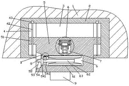
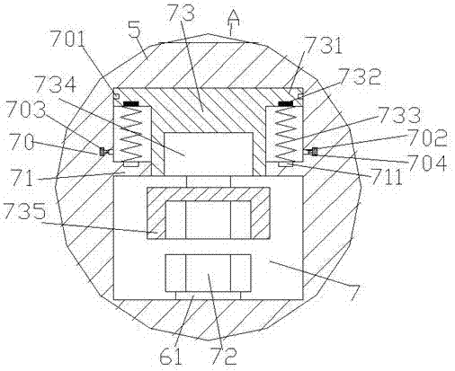
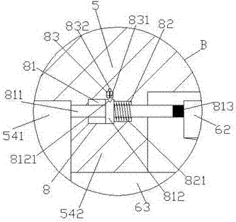
[0022] Such as Figure 1-Figure 6 As shown, a novel air purification device of the present invention includes a base body 1 and a machine base 2 disposed in the base body 1, the inner bottom of the base body 2 is provided with a container 3, and the container 3 is provided with Lifting member 5, the outer wall on the left side of the lifting member 5 is provided with a pick-up area 52, the inner block 54 of the lifter 5 on the right side of the pick-up area 52, and the lifting block 54 on the right side of the block 54 A first steering chamber 6 is provided in the member 5, and a second partition plate 542 is provided between the first steering chamber 6 and the clamping block 54. In the lifting member 5 above the first steering chamber 6 A second turning cavity 7 is provided, and a first separation plate 71 is arranged in the second turning cavity 7, and a convex body 73 is arranged in the second turning cavity 7 above the first separation plate 71, so that The top of both s...
PUM
 Abstract
Description
Claims
Application Information