Hidden rack lifting type illuminating mechanism

A lifting and hidden technology, which is applied in the field of hidden rack lifting lighting mechanism, can solve the problems of fixed structure, unrealizable illumination effect, and inability to realize up and down position adjustment, etc., to achieve good illumination effect

Inactive Publication Date: 2017-10-20
FOSHAN HUAPU RUILIAN ELECTROMECHANICAL TECH CO LTD
View PDF0 Cites 1 Cited by
  • Summary
  • Abstract
  • Description
  • Claims
  • Application Information

AI Technical Summary

Problems solved by technology

[0002] Existing lighting fixtures are generally directly fixed on the equipment, and its structure is fixed, so it is impossible to adjus

Method used


Image

  • Hidden rack lifting type illuminating mechanism
  • Hidden rack lifting type illuminating mechanism

Examples


Example Embodiment

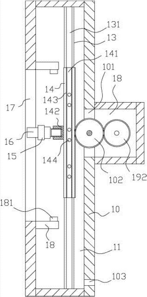
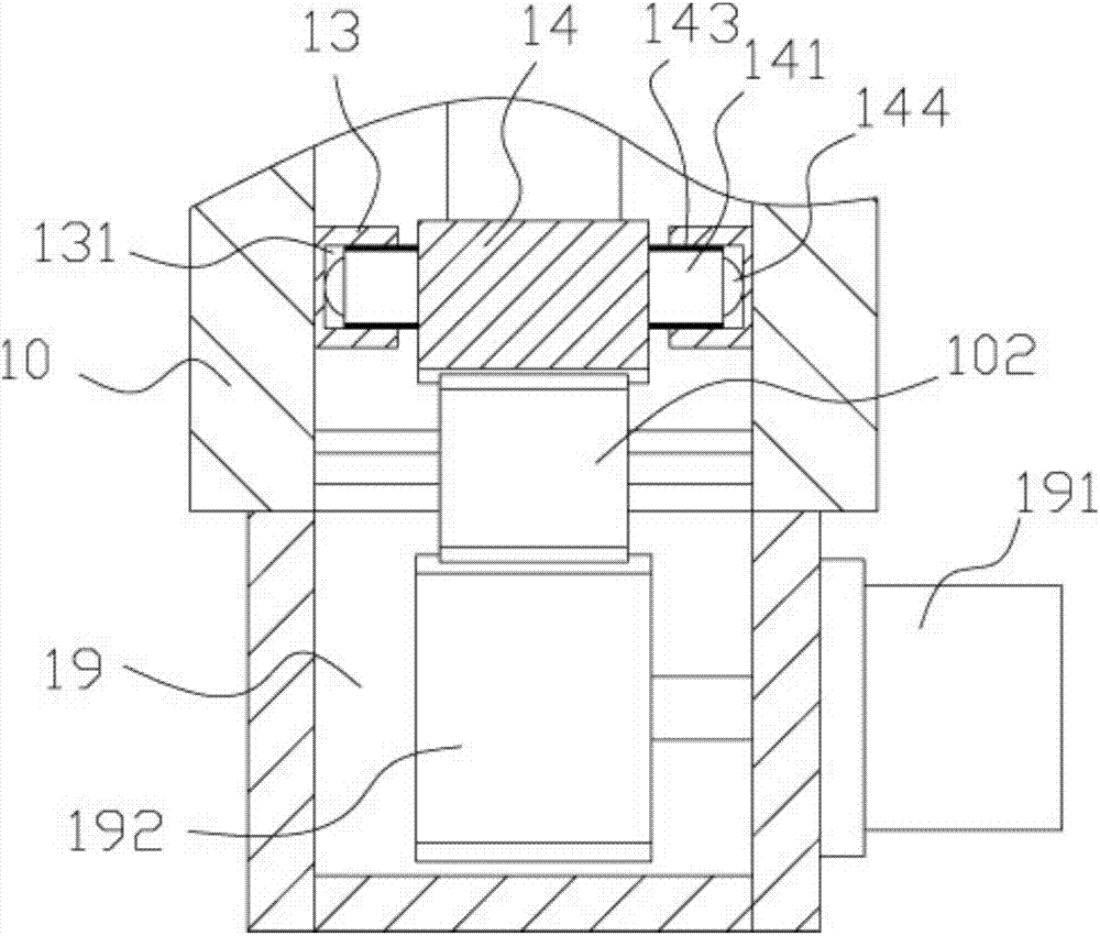
[0016] Example: see Figure 1 to Figure 2 As shown, a hidden rack-mounted lifting lighting mechanism includes a main casing 10, the middle of the main casing 10 has a main cavity 11, and the middle of the left and right inner side walls of the main cavity 11 is fixed with a guide bar 13, and The middle of the opposite wall surfaces of the two guide bars 13 has a vertical guide groove 131, the rack 14 is located between the two guide bars 13, and the left and right side walls of the rack 14 are provided with sliding blocks 141, and the sliding blocks 141 are inserted in the corresponding In the vertical guide groove 131, the middle front wall of the rack 14 has a connecting portion 142, a connecting block 15 is fixed on the connecting portion 142, and a lighting lamp 16 is fixed on the connecting block 15, and the irradiation part of the lighting lamp 16 is inserted into the host In the vertical through groove 17 provided in the middle of the front plate body of the shell 10;

[...


PUM


Abstract

The invention discloses a concealed rack lifting lighting mechanism, which comprises a main casing. There is a vertical guide groove in the middle of the opposite wall, the rack is between the two guide bars, there are sliding blocks on the left and right side walls of the rack, the sliding blocks are inserted into the corresponding vertical guide grooves, and the front of the middle of the rack There is a connecting part on the wall, and a connecting block is fixed on the connecting part, and an illuminating lamp is fixed on the connecting block, and the illuminating part of the illuminating lamp is inserted into the vertical through groove provided in the middle part of the front plate of the main casing; the main casing The outer connecting shell is fixed on the rear wall surface of the middle part of the rear plate body, and the middle part of the rear plate body of the main casing has a through groove, and the intermediate transmission gear is in the through groove. It can be fixed in the wall or in the cabinet, and it can realize the adjustment of the upper and lower positions for dynamic irradiation, which can meet different irradiation and irradiation effects.

Description

Technical field: [0001] The invention relates to the technical field of lighting equipment, and more specifically relates to a hidden rack lifting lighting mechanism. Background technique: [0002] Existing lighting fixtures are generally directly fixed on the equipment, and their structure is fixed, so that the up and down position adjustment cannot be realized to meet the illumination requirements, and at the same time, some characteristic illumination effects cannot be realized. Invention content: [0003] The purpose of the present invention is to address the deficiencies of the prior art, and to provide a hidden rack lifting lighting mechanism, which can be fixed in the wall or in the cabinet, and it can realize dynamic irradiation by adjusting the upper and lower positions. Well, different irradiation and irradiation effects can be satisfied. [0004] Technical solutions of the present invention are as follows: [0005] A hidden rack lifting lighting mechanism, inc...

Claims


Application Information

Patent Timeline
IPC IPC(8): F21V21/15F21V21/34
CPCF21V21/15F21V21/34
Inventor 杨海丹
Owner FOSHAN HUAPU RUILIAN ELECTROMECHANICAL TECH CO LTD
Why Eureka
Try Eureka