Fingerprint Sensing Device

A technology for sensing equipment and fingerprints, which is applied in the direction of acquiring/arranging fingerprints/palmprints, capacitance measurement, instruments, etc. It can solve problems such as slow frame rate, direct coupling problems, lack of sensitivity, etc., to increase frame rate and increase reliability performance, the effect of high transmit power

Active Publication Date: 2020-04-14
SILEAD
View PDF5 Cites 0 Cited by
  • Summary
  • Abstract
  • Description
  • Claims
  • Application Information

AI Technical Summary

Problems solved by technology

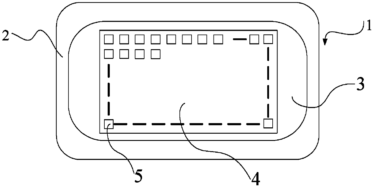
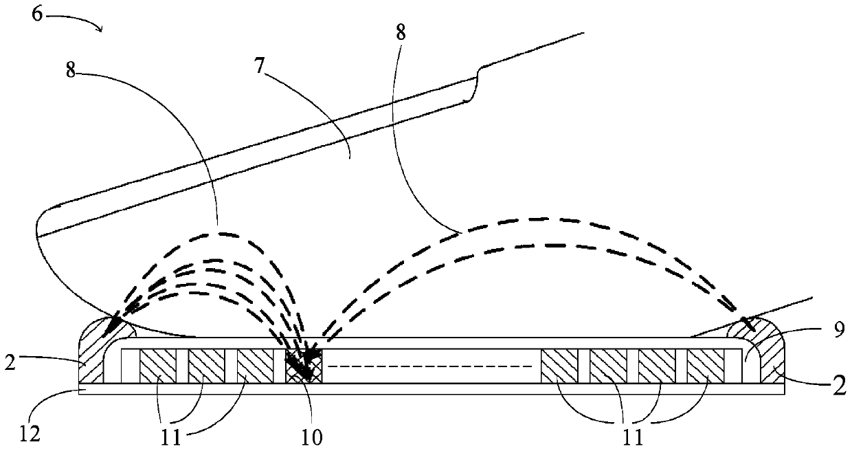
[0004] However, there are many disadvantages when bezel 2 is used as a strong external AC signal source
First, it increases the material cost of the fingerprint sensor 1 and the complexity of the manufacturing process
Second, it reduces the product yield of fingerprint sensors
Third, when the entire module is integrated into an electronic device (such as being placed on a mobile phone or similar device), the bezel 2 makes the industrial design (e.g., structure and appearance) of the device more difficult and may interfere with the mechanical requirements of the device Mismatch
A sensor unit either sends a signal or receives a signal, but not both
Such methods suffer from slower frame rates because the unit has to switch between transmit and receive modes
Furthermore, since only some units transmit signals, such methods do not provide sufficient transmit power and thus lack the necessary sensitivity for specific fingerprint applications
Furthermore, direct coupling between a receiving unit and a nearby transmitting unit can be problematic for such an approach

Method used


Image

  • Fingerprint Sensing Device
  • Fingerprint Sensing Device
  • Fingerprint Sensing Device

Examples


Embodiment Construction

[0018] For the purposes of promoting an understanding of the principles of the disclosure, reference will now be made to the embodiments illustrated in the drawings, and specific language will be used to describe the embodiments. It should be understood, however, that no limitation of the scope of the present disclosure is intended. Any changes and further modifications to the described devices, systems, methods, and any further applications of the principles of the present disclosure will generally be readily apparent to those skilled in the art to which the present disclosure pertains. For example, features, components and / or steps described with respect to one embodiment may be combined with features, components and / or steps described with respect to other embodiments of the present disclosure to form yet another embodiment of an apparatus, system or method according to the present disclosure. embodiment, even if such a combination is not explicitly shown. Additionally, fo...


PUM


Abstract

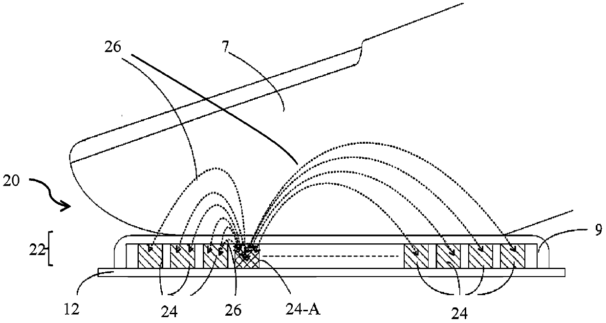
Fingerprint sensing device. Fingerprint sensor array with duplex sensor cells. A fingerprint sensing device includes a substrate and an array of sensor cells formed on the substrate. These sensor units are divided into groups. Each group is associated with a group identifiable signal. The sensor units in each group are configured to transmit group-identifiable signals of the respective group, and are also configured to simultaneously receive group-identifiable signals transmitted by sensor units in other groups. The set of identifiable signals are orthogonal with respect to each other.

Description

technical field [0001] The present disclosure generally relates to electronic devices capable of sensing events. More particularly, but not in a limiting manner, the present disclosure relates to a sensing device and a driving and sensing method for a sensing device such as a fingerprint sensor and a system thereof. Background technique [0002] figure 1 is a top view of the fingerprint sensor 1 mainly including a bezel 2 and a sensing part 3 . Bezel 2 provides a strong external alternating current (AC) signal. The sensing section 3 has a control circuit, a sensor array 4, and the like. The sensor array 4 includes M×N sensor units 5 serving as receiving units for AC signals. [0003] figure 2 is the cross section of fingerprint sensor 1 Figure 6 , shows the operation of the fingerprint sensor 1. The finger 7 touches the fingerprint sensor 1 . The AC signal 8 from the bezel 2 passes through the finger 7 and the protective layer 9 and reaches the scanning sensor unit...

Claims


Application Information

Patent Timeline
Patent Type & Authority Patents(China)
IPC IPC(8): G06K9/00
CPCG06V40/1306H01L27/14609G06V40/1335G01R27/2605
Inventor 程泰毅
Owner SILEAD
Why Eureka
Try Eureka