High-power microwave mode conversion speaker antenna

A high-power microwave and mode-converting technology, applied in the field of radiation antennas, can solve the problems that horn antennas cannot be directly used to transmit high-power microwaves, and the axial direction is not compact enough.

Active Publication Date: 2017-11-21
NAT UNIV OF DEFENSE TECH
View PDF1 Cites 11 Cited by
  • Summary
  • Abstract
  • Description
  • Claims
  • Application Information

AI Technical Summary

Problems solved by technology

[0005] The technical problem to be solved by the present invention is to provide a new type of high-power microwave mode conversion horn antenna, which has a compact structure, coaxial input and output, and high gain, so as to solve the problem that the current horn antenna cannot be directly used to transmit high-power microwaves, and Axial not compact enough, etc.

Method used


Image

  • High-power microwave mode conversion speaker antenna
  • High-power microwave mode conversion speaker antenna
  • High-power microwave mode conversion speaker antenna

Examples


Embodiment 1

[0035] The specific design dimensions of the mode conversion lens embodiment in the high power microwave mode conversion horn antenna with a high power microwave frequency of 12 GHz (that is, the frequency of the input microwave source is 12 GHz, and the corresponding microwave wavelength is 25 mm):

[0036] The first matching layer 21 , the filling medium 23 , and the second matching layer 24 are made of epoxy resin, and the relative dielectric constant of the epoxy resin is 4. At this frequency, the semi-major axis a1 of the first elliptical cylindrical hole 221 should satisfy 3.57mm3.679mm, and the side length d of the regular hexagon in the cross section of the mode conversion unit should satisfy Select the side length d=7.56mm of the regular hexagon, and after the microwave is transmitted through the first matching layer 21, the first elliptical cylindrical hole 221 and the first transition hole 222, the microwave from the linearly polarized TE mode to the right-handed cir...

Embodiment 2

[0039] The specific design dimensions of the embodiment of the high-power microwave mode-converted horn antenna with the high-power microwave frequency of 14.2GHz (that is, the frequency of the input microwave source is 14.2GHz, and the corresponding microwave wavelength is 21.03mm):

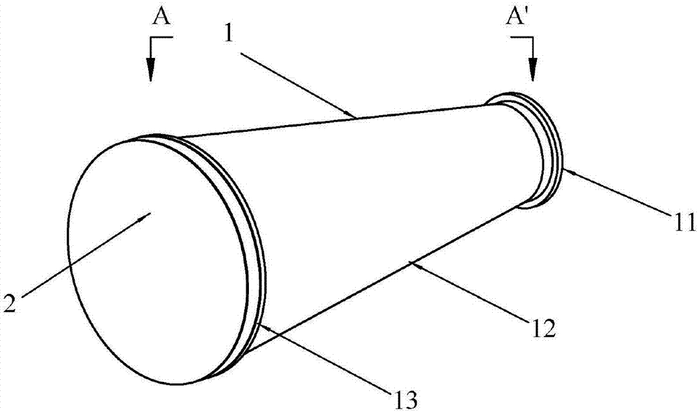
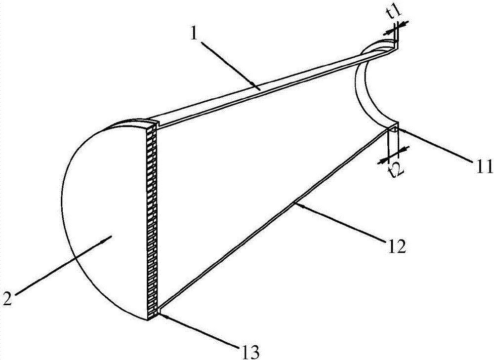
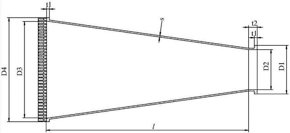
[0040] The horn antenna 1 adopts a conical horn antenna, wherein the circular waveguide in the antenna main body 12 and the inner diameter of the conical waveguide near the microwave source end D2=140mm, the length of the circular waveguide t2=30mm, and the inner diameter of the conical waveguide away from the microwave source end D3=340mm, the axial length l=703mm; the outer diameter of the first flange 11 D1=170mm, the outer diameter of the second flange 13 D4=370mm, the thickness of the first flange 11 and the second flange 13 are both t1=10mm, the waveguide Wall thickness s=5mm; the diameters of the first matching layer 21, the second matching layer 24 and the metal disc 22 are equal to the o...


PUM


Abstract

The invention discloses a high-power microwave mode conversion speaker antenna and is intended to solve the problems, for instance, an existing speaker antenna is unable to be directly used to transmit high-power microwave and is poor in axial compactness. The high-power microwave mode conversion speaker antenna is composed of a speaker antenna and a mode conversion lens; the speaker antenna is composed of 2 flanges and an antenna body; the mode conversion lens is composed of a first matching layer, a metal disc, a filling medium, and a second matching layer; the metal disc is formed by combining a plurality of mode conversion units in honeycomb arrangement, the cross section of each mode conversion unit is regularly hexagonal, and as seen from the cross section of the metal disc, the regular hexagons are tightly arranged in a circle shape; prism bodies, with regularly hexagonal section, of the mode conversion units are each provided with 5 holes, and the filling medium fills the 5 holes evenly. The high-power microwave mode conversion speaker antenna is better in axial compactness, may ensure lossless transmission of microwave, and has high power capacity, gain and aperture efficiency.

Description

technical field [0001] The invention relates to a radiation antenna in the technical field of high-power microwaves, in particular to a high-power microwave horn antenna capable of mode conversion. Background technique [0002] At present, the microwave modes generated by most high-power microwave sources (such as virtual cathode oscillators, relativistic return wave tubes, magnetic insulated wire oscillators, etc.) are rotational axisymmetric modes, such as the TM of the circular waveguide. 01 Die, TE 01 mode and coaxial waveguide TEM mode, etc. These modes have rotational symmetry around the waveguide axis due to the field distribution and polarization direction on the waveguide cross-section. If the traditional horn antenna is directly launched or excited, it will produce a ring-shaped far-field pattern with zero axial direction. Its energy dispersion, gain Low, it is not conducive to the directional launch and transmission of high-power microwaves. [0003] In order t...

Claims


Application Information

Patent Timeline
Patent Type & Authority Applications(China)
IPC IPC(8): H01Q13/02H01Q15/02H01Q19/06
CPCH01Q13/02H01Q15/02H01Q19/06
Inventor 袁成卫孙云飞贺军涛张强张晓萍冯加怀李志强王弘刚
Owner NAT UNIV OF DEFENSE TECH
Why Eureka
Try Eureka