A variable focus camera module
A technology of camera module and focal length, which is applied in the field of photography to achieve the effect of simple structure, small volume, and light and thin volume
- Summary
- Abstract
- Description
- Claims
- Application Information
AI Technical Summary
Problems solved by technology
Method used
Image
Examples
Embodiment 1
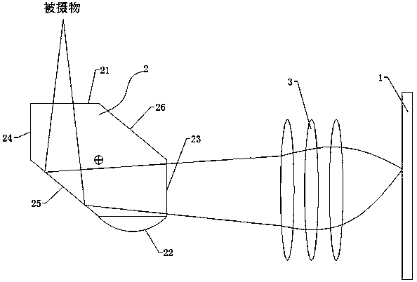
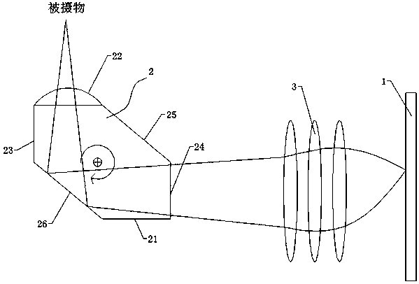
[0025] Such as figure 1 with 2 As shown, a camera module with variable focal length includes an imaging unit 1 and a rotatable reflective prism 2 arranged in the light-incoming direction of the imaging unit 1, and the light of the subject is reflected by the reflective prism 2 projected onto the imaging unit 1 for imaging; the reflective prism 2 includes a first incident surface 21 and a second incident surface 22 for the light to enter, a first exit surface 23 and a second exit surface for the light to exit 24 and the first reflective surface 25 and the second reflective surface 26 for light reflection; the focal lengths of the first incident surface 21 and the second incident surface 22 are different.
[0026] Such as figure 1 As shown, before the rotation of the reflective prism 2, its first incident surface 21 faces the subject, and the first outgoing surface 23 faces the imaging unit 1. The light enters from the first incident surface 21 and passes through the After be...
Embodiment 2
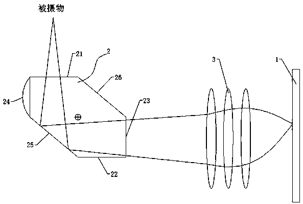
[0036] Such as image 3 with 4 As shown, a camera module with variable focal length includes an imaging unit 1 and a rotatable reflective prism 2 arranged in the light-incoming direction of the imaging unit 1, and the light of the subject is reflected by the reflective prism 2 projected onto the imaging unit 1 for imaging; the reflective prism 2 includes a first incident surface 21 and a second incident surface 22 for the light to enter, a first exit surface 23 and a second exit surface for the light to exit 24 and the first reflective surface 25 and the second reflective surface 26 for light reflection; the focal lengths of the first exit surface 23 and the second exit surface 24 are different.
[0037] Among them, such as image 3 As shown, before the rotation of the reflective prism 2, its first incident surface 21 faces the subject, and the first outgoing surface 23 faces the imaging unit 1. The light enters from the first incident surface 21 and passes through the Afte...
Embodiment 3
[0047] Such as Figure 5 with 6 As shown, a camera module with variable focal length includes an imaging unit 1 and a rotatable reflective prism 2 arranged in the light-incoming direction of the imaging unit 1, and the light of the subject is reflected by the reflective prism 2 projected onto the imaging unit 1 for imaging; the reflective prism 2 includes a first incident surface 21 and a second incident surface 22 for the light to enter, a first exit surface 23 and a second exit surface for the light to exit 24 and the first reflective surface 25 and the second reflective surface 26 for light reflection; the focal lengths of the first incident surface 21 and the second incident surface 22 are different, and, the first exit surface 23 and the second exit surface 24 has a different focal length.
[0048] Among them, such as Figure 5 As shown, before the rotation of the reflective prism 2, its first incident surface 21 faces the subject, and the first outgoing surface 23 fac...
PUM
 Abstract
Description
Claims
Application Information
 - R&D
- Intellectual Property
- Life Sciences
- Materials
- Tech Scout
- Unparalleled Data Quality
- Higher Quality Content
- 60% Fewer Hallucinations
Browse by: Latest US Patents, China's latest patents, Technical Efficacy Thesaurus, Application Domain, Technology Topic, Popular Technical Reports.
© 2025 PatSnap. All rights reserved.Legal|Privacy policy|Modern Slavery Act Transparency Statement|Sitemap|About US| Contact US: help@patsnap.com


