Check patentability & draft patents in minutes with Patsnap Eureka AI!

AP error detection method and device and electronic equipment

A fault detection and fault technology, applied in the field of communication, can solve problems such as inconvenience to users, user inconvenience, and provision of radio frequency services

Active Publication Date: 2018-01-05
NEW H3C TECH CO LTD
View PDF5 Cites 7 Cited by
  • Summary
  • Abstract
  • Description
  • Claims
  • Application Information

AI Technical Summary

Problems solved by technology

[0004] In view of this, the purpose of the present disclosure is to provide a fault detection method, device and electronic equipment, so as to alleviate the problem in the prior art that the AC cannot find out in time when the AP has a radio frequency fault when the user tries to associate with the AP. Technical problems that will not be able to provide radio frequency services to users and cause inconvenience to users

Method used


Image

  • AP error detection method and device and electronic equipment
  • AP error detection method and device and electronic equipment
  • AP error detection method and device and electronic equipment

Examples


Embodiment approach

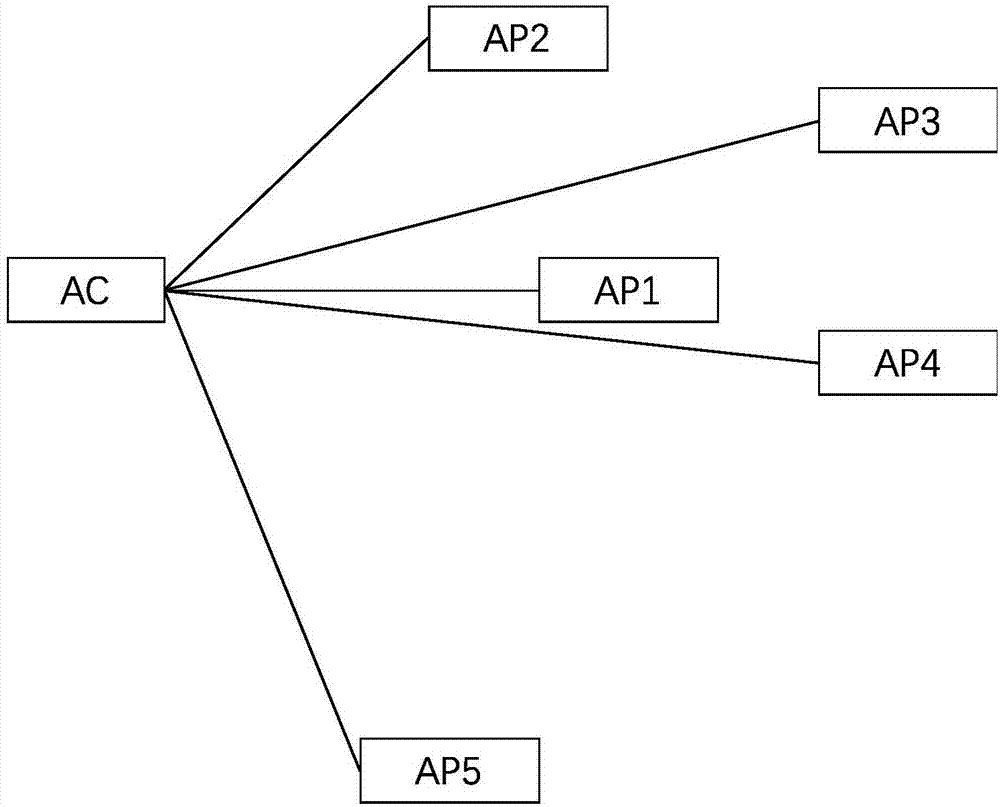
[0049] An optional implementation manner is as follows: among the APs sending the neighbor status list, the first N APs with high signal strengths of the APs to be detected can be determined as neighbor APs of the AP to be detected, where N is a positive integer; For example, if figure 2 As shown, if AP1 is the AP to be detected, then if AP2, AP3, AP4, and AP5 can all detect the signal strength information of AP1, since the distances between AP1 and AP2, AP3, AP4, and AP5 may be different, AP2, AP3 , the signal strength of AP1 recorded in the neighbor state tables of AP4 and AP5 may also be different, so in the embodiment of the present disclosure, the signal strength of AP1 obtained from the neighbor state tables of AP2, AP3, AP4 and AP5 can be Sorting in order of size, select the N neighbors with the highest signal strength as AP1's neighbors, if N=3, then the three neighbors of AP1 are AP2, AP3 and AP4, where N is a positive integer.

[0050] Another optional implementation...


PUM


Abstract

The invention discloses an AP error detection method and device and electronic equipment. The method includes the steps of receiving neighbor state lists sent from multiple APs; according to the signal intensity information, carried in the neighbor state lists, of an AP to be detected, determining a neighbor AP of the AP to be detected from the APs; if it is determined that the signal intensity ofthe AP to be detected is not sent by the neighbor AP within a preset aging time, determining that the AP to be detected has a radio frequency error; therefore, the AP error detection method and device and the electronic equipment can achieve the technical effects that when it is determined that the neighbor AP does not send the signal intensity of the AP to be detected within the preset aging time, whether or not the AP to be detected breaks down can be automatically judged, and more convenience is provided for finding out broken down APs in time.

Description

technical field [0001] The present disclosure relates to the technical field of communications, and in particular to an AP fault detection method, device and electronic equipment. Background technique [0002] With the large-scale development of wireless networks, when a large number of APs (Access Points, wireless access points) are deployed, the AC (Access Controller, Access Controller) generally configures and manages the software upgrades and radio frequency parameters of each subordinate AP in a centralized manner. All radio frequency parameters and upgrade software are stored on the AC and distributed to each AP by the AC. The AP and the AC use a CAPWAP (Controlling and Provisioning of Wireless Access Point) tunnel for communication. Each AP Send wireless signals according to the configured radio frequency parameters to provide services for clients. [0003] However, when any AP radio frequency fails, because the AP can normally communicate with the AC through the CAP...

Claims


Application Information

Patent Timeline
IPC IPC(8): H04W24/08
Inventor 吴宝平聂树伟
Owner NEW H3C TECH CO LTD
Features
  • R&D
  • Intellectual Property
  • Life Sciences
  • Materials
  • Tech Scout
  • Unparalleled Data Quality
  • Higher Quality Content
  • 60% Fewer Hallucinations
Learn More