Wire winding mechanism and moving platform with same

A technology of winding mechanism and motion platform, which is applied in the directions of transportation and packaging, conveying filamentous materials, thin material processing, etc., and can solve problems such as use restrictions, unsuitable cable use, signal transmission interference, etc.

Inactive Publication Date: 2018-01-16
HIWIN MIKROSYST
View PDF5 Cites 1 Cited by
  • Summary
  • Abstract
  • Description
  • Claims
  • Application Information

AI Technical Summary

Problems solved by technology

[0003] In the related technologies that are used to avoid twisting and breaking of the wire body itself, those using air pressure rotary joints can only be implemented on the delivery pipeline of compressed air, although those using electronic slip rings and electric brushes can be used in the technical field of power supply However, due to the noise associated with its operation, it will cause signal transmission interference, so it is not suitable for the use of cables for signal transmission. , which can only be implemented in specific technical fields, but cannot be applied to other technical fields
[0004] Furthermore, for example, when the wire body is used as a channel for electric energy or signal transmission, the known technology for winding it needs to be as follows: figure 1 As shown, a connector such as a socket 4 is provided on the turntable 2 for connection with external lines, but when retracting, since the socket 4 will rotate with the turntable 2, in order to avoid twisting the external lines , it is necessary to separate the external line before the turntable rotates, so that the line body can be retracted or pulled out, resulting in restrictions on its use

Method used


Image

  • Wire winding mechanism and moving platform with same
  • Wire winding mechanism and moving platform with same
  • Wire winding mechanism and moving platform with same

Examples


Embodiment Construction

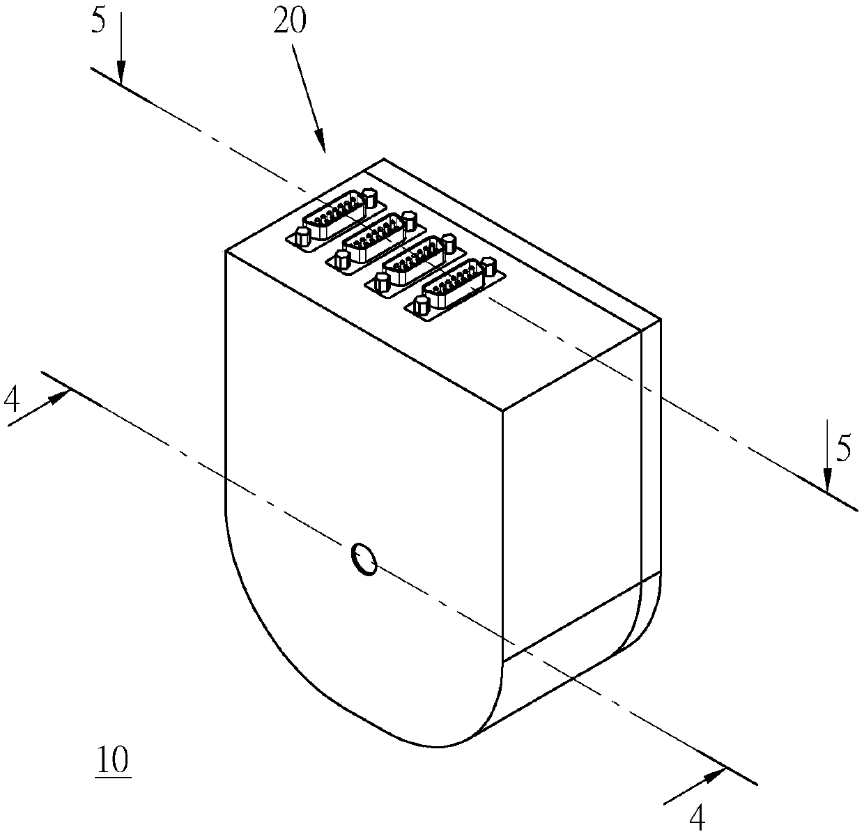
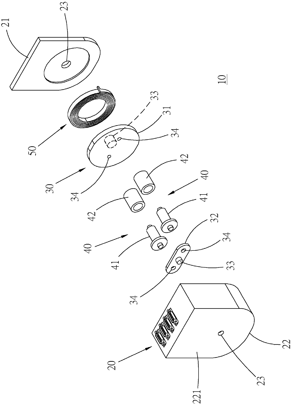
[0025] First, see Figure 2 to Figure 5 As shown, a wire winding mechanism 10 is provided in an embodiment of the present invention, which mainly includes a housing base 20 , a base member 30 , two support members 40 and an elastic member 50 .

[0026] The housing base 20 has an end body 21 , a housing 22 and two shaft holes 23 . The end body 21 is in the shape of a plate, and the shell 22 is in the shape of a hollow cap, and the end body 21 and the shell 22 are docked with each other, so that an appropriate volume of accommodation space is formed between the end body 21 and the shell 22 to accommodate components other than the shell seat and The line body to be rolled up is contained therein. The two shaft holes 23 are coaxially and correspondingly disposed on the end body 21 and a pair of shell plates 221 of the shell 22 away from the end body.

[0027] The base part 30 is located in the receiving space of the shell base 20 and has a turntable 31 , an adapter seat 32 , two...


PUM


Abstract

The invention relates to a wire winding mechanism and a moving platform with the same. The moving platform includes a fixed base, a mobile base, the wire winding mechanism and a wire body, and the mobile base is arranged on the fixed base in a sliding mode and can move back and forth in a linear direction; the wire winding mechanism is arranged on the fixed base and composed of a base piece rotating around a main shaft and two supporting pieces which are mutually spaced and arranged on the axial ends, corresponding to the base piece, of the main shaft respectively; the wire body is arranged inthe wire winding mechanism in a wound mode, and one end of the wire body is electrically connected with the mobile base. According the wire winding mechanism and the moving platform with the same, multiple rotating shafts are adopted to wind the wire body, and by adopting a main shaft component to serve as a revolution center shaft and adopting two branch shaft components to serve as rotation center shafts respectively, the wire body is wound on each branch shaft component, and therefore the wire body can be released or wound by means of the rotation of the main shaft component, and through rotation of each branch shaft component, relative movement between the branch shaft components and the wire body can be achieved, so that the wire body can move smoothly.

Description

technical field [0001] The present invention relates to the winding technology of flexible wires, in particular to a wire winding mechanism and a motion platform with the winding mechanism. Background technique [0002] The known technology of rolling up flexible lines, ropes, ropes, water pipes, air pipes, cables, electric wires and optical fibers with a turntable, its specific example is as figure 1 As shown, the thread body 1 is fixed on the turntable 2 on one side, and is rewound on the rotating shaft 3 of the turntable 2, thereby, when the turntable 2 and the rotating shaft 3 rotate, the thread body 1 can be wound synchronously. Winding on the rotating shaft 3, but because the wire body 1 is prone to breakage due to twisted wires when it is rewound, in order to reduce the occurrence of other things, such as air pressure rotary joints, electronic sliders, etc. are used in the prior art. Rotary connection technologies such as rings and brushes, the twisting and twisting ...

Claims


Application Information

Patent Timeline
Patent Type & Authority Applications(China)
IPC IPC(8): B65H54/06B65H54/70
Inventor 卓永财周琦斌
Owner HIWIN MIKROSYST
Why Eureka
Try Eureka