Supercharge Your Innovation With Domain-Expert AI Agents!

Parallel slide gate valves and related methods

一种滑动闸门、平坦的技术,应用在闸门阀领域,能够解决不能移动等问题

Active Publication Date: 2018-02-27
FLOWSERVE MANAGEMENT CO
View PDF7 Cites 1 Cited by
  • Summary
  • Abstract
  • Description
  • Claims
  • Application Information

AI Technical Summary

Problems solved by technology

[0007] Failure of the bracket 28 may cause the halves 24a, 24b to become disengaged from each other such that the gate 24 cannot move back into the inner passage 20 to close the gate valve 10

Method used


Image

  • Parallel slide gate valves and related methods
  • Parallel slide gate valves and related methods
  • Parallel slide gate valves and related methods

Examples


Embodiment Construction

[0015] The illustrations presented herein are not actual views of any particular valve, but are idealized representations only, which are used to describe example embodiments of the present disclosure. Furthermore, elements that are common between the figures may maintain the same number designation.

[0016] As used herein, the term "valve" means and includes any device configured to regulate, direct, or control the flow of a fluid (eg, liquid and / or gas).

[0017] As used herein, the term "obturator" means and includes a valve closure member, such as a disc, gate, cock or ball. For example, in a gate valve, the obturator is a translational gate. An obturator may comprise one or more components.

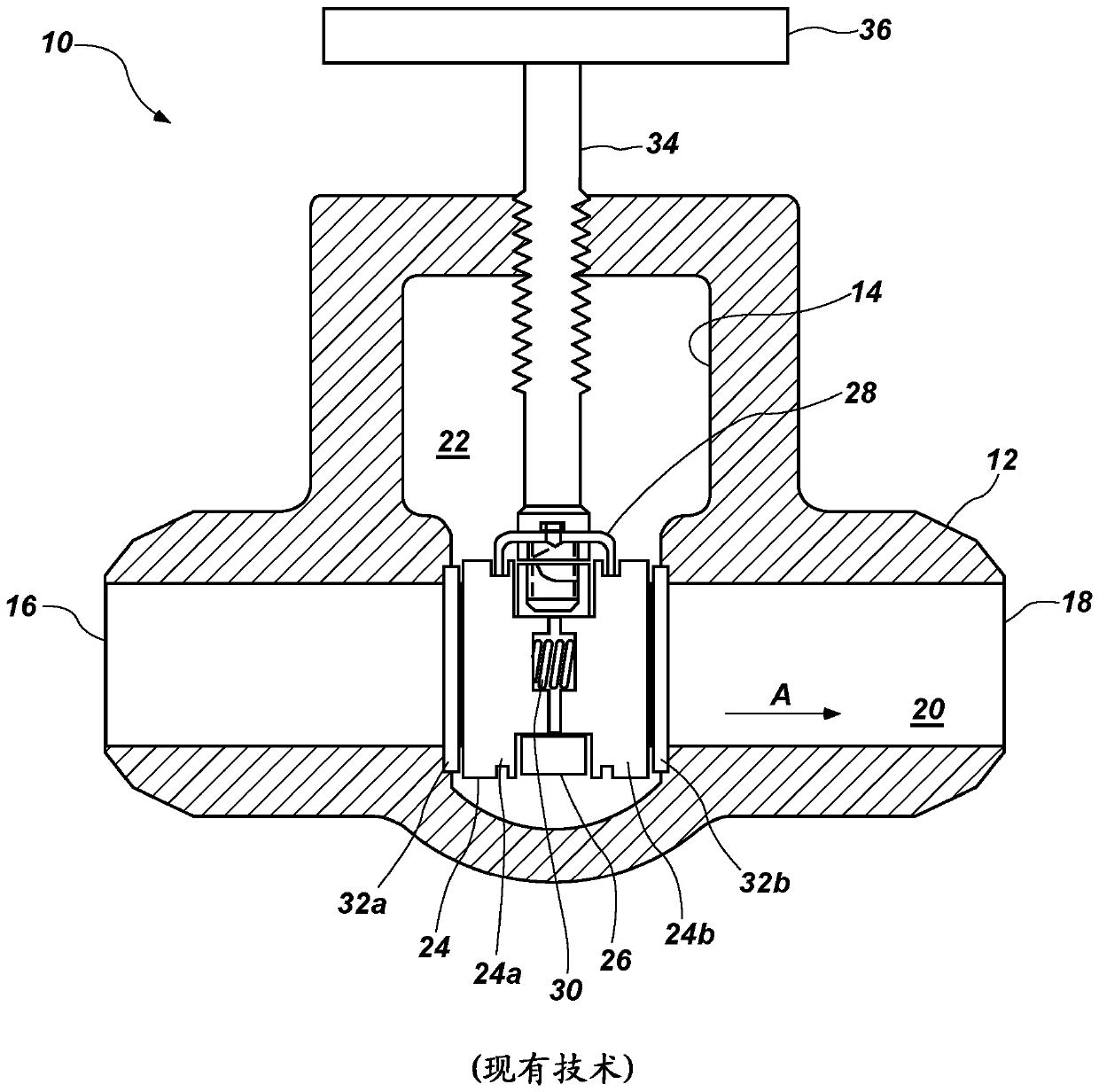
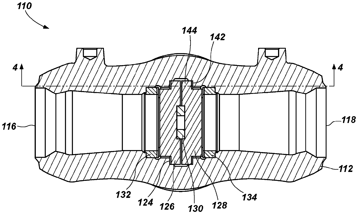
[0018] Disclosed herein is a parallel sliding gate valve configured to operate without a bracket holding the two halves of the gate together. The valve may have fewer moving parts than conventional parallel sliding gate valves, and may thus be more robust and less prone to catast...


PUM


Abstract

A parallel slide gate valve includes a valve body comprising an interior surface, and an obturator therein. A portion of the interior surface defines a groove having a longitudinal axis oriented substantially peipendicular to a direction of flow through the valve body. The groove has a first width at a first end proximate to the fluid flow path and a second width at a second end distal from the fluid flow path, the second width smaller than the first width. The obturator is at least partially within the at least one groove. The obturator is configured to translate from the first end of the atleast one groove toward the second end of the at least one groove as the obturator moves from a closed position to an open position.

Description

[0001] priority statement [0002] This application claims the benefit of the filing date of U.S. Patent Application Serial No. 14 / 696,321, filed April 24, 2015, entitled "Parallel Slide Gate Valves and Related Methods." technical field [0003] Embodiments of the present disclosure relate to valves with translatable obturators, such as gate valves with parallel sliding gates. Background technique [0004] Many valve types are used to stop and control fluid flow in pipes or other flow paths. The various types of valves offer certain advantages and disadvantages. Some valve types include plug valves, ball valves, stop or globe valves, angle valves, butterfly valves, and gate valves. [0005] Wedge gate valves have a gate shaped as a wedge with two oppositely inclined flat faces (usually metal) each sealing against a portion of a seat of the valve's body. Both the face of the gate and the corresponding surface of the valve seat are typically machined to allow the gate to f...

Claims


Application Information

Patent Timeline
Patent Type & Authority Applications(China)
IPC IPC(8): F16K3/02F16K3/16F16K3/18F16K3/316F16K25/00F16K27/04
CPCF16K3/0281F16K3/16F16K3/18F16K3/316F16K25/005F16K27/044
Inventor R.J.格拉德尔
Owner FLOWSERVE MANAGEMENT CO
Features
  • R&D
  • Intellectual Property
  • Life Sciences
  • Materials
  • Tech Scout
  • Unparalleled Data Quality
  • Higher Quality Content
  • 60% Fewer Hallucinations
Learn More