Unlock instant, AI-driven research and patent intelligence for your innovation.

Cartridge Fluid Dispensing Equipment

A kind of equipment and fluid technology, applied in the field of fluid distribution equipment, can solve the problems of inability to distribute high-viscosity materials and low-viscosity materials, and increase the risk of contamination

Inactive Publication Date: 2021-01-15
NORDSON CORP
View PDF8 Cites 0 Cited by
  • Summary
  • Abstract
  • Description
  • Claims
  • Application Information

AI Technical Summary

Problems solved by technology

However, these devices require extensive handling by the operator to load the fluid, which increases the risk of contamination
Additionally, many well-known devices are unable to dispense both high-viscosity and low-viscosity materials from the cartridge
Finally, many well-known devices do not include sensing and feedback control

Method used


Image

  • Cartridge Fluid Dispensing Equipment
  • Cartridge Fluid Dispensing Equipment
  • Cartridge Fluid Dispensing Equipment

Examples


Embodiment Construction

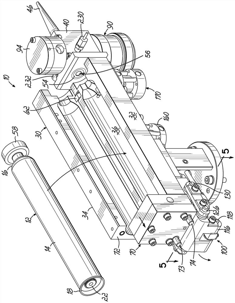
[0074] figure 1 and figure 2Shown is a dispensing apparatus 10, also referred to as a dispenser 10, for dispensing various types of fluids, including but not limited to polysulfides, polyurethanes, epoxies, adhesives, and silicones. In this embodiment, dispensing device 10 is a cartridge dispenser utilizing a fluid cartridge 12 comprising a cartridge body 14 having a distal end 16, a proximal end 18 adapted to receive air pressure from dispensing device 10, and A fluid space 20 extends between the distal end 16 and the proximal end 18 . A plunger 22 is positioned in the fluid space 20 and is movable towards the distal end 16 under force applied by air pressure. The dispensing device 10 includes a cartridge holder 30 including a first clamshell member 32 and a second clamshell member 34 for receiving the cartridge 12 in a cartridge holding space 36 . At least one of the clamshell members 32 , 34 is movable toward and away from the other of the clamshell members 32 , 34 for ...


PUM


Abstract

A dispensing device (10) is described having various features. The dispensing device may receive a cartridge (12) having a movable plunger configured to direct fluid through a dispensing valve. The plunger may be able to move under the force exerted by air pressure. The cartridge (12) can be inserted into the dispensing device using a clamp and seal mechanism (70), and the cartridge (12) can be released using a cartridge ejector.

Description

[0001] related application [0002] This application claims priority to U.S. Provisional Patent Application No. 62 / 174,121, filed June 11, 2015, and U.S. Provisional Application No. 62 / 276,647, filed January 8, 2016, both of which are hereby incorporated by reference in their entirety. into this article. technical field [0003] The present disclosure relates generally to fluid dispensing devices, and more particularly to dispensing fluid from a cartridge having a movable plunger configured to direct the fluid through a dispensing valve. Background technique [0004] Various fluid dispensing devices are well known. However, these devices require extensive handling by the operator to load the fluid, which increases the risk of contamination. Additionally, many known devices are unable to dispense both high and low viscosity materials from the cartridge. Finally, many well known devices do not include sensing and feedback control. Accordingly, there is a need for a lightwe...

Claims


Application Information

Patent Timeline
Patent Type & Authority Patents(China)
IPC IPC(8): B05C11/10B05C11/11
CPCB05C11/1013B05C11/1031B05C11/11B05C5/02B05C5/0233B05C17/0103B05C17/0146B05C17/015G01L19/003G01L19/147
Inventor 杰弗里·J·格拉纳贾斯汀·霍尔威廉·C·佩托二世杰里·R·鲁唐托马斯·R·图德
Owner NORDSON CORP