Optical fiber coiling device group

A technology of optical fiber coiling and device assembly, which is applied in optics, light guides, optical components, etc., can solve problems such as uneven heat dissipation, visual blind spots, and large errors, and achieve efficient and high-quality water-cooled heat dissipation and reduce labor costs.

Active Publication Date: 2018-03-13
EZHOU INST OF IND TECH HUAZHONG UNIV OF SCI & TECH +1
View PDF7 Cites 5 Cited by
  • Summary
  • Abstract
  • Description
  • Claims
  • Application Information

AI Technical Summary

Problems solved by technology

[0002] Aiming at the problems of low efficiency, high cost, easy damage and large error existing in the existing manual optical fiber coiling method, a high-efficiency, high-quality, simple and accurate mechanical coiling method is proposed
[0003] Aiming at the problems of large volume, uneven heat dissipation, and visual blind spots in the existing water-cooled cylinder heat dissipation method, a planar coil method with small size, uniform heat dissipation, and omni-directional monitoring is proposed.

Method used


Image

  • Optical fiber coiling device group
  • Optical fiber coiling device group
  • Optical fiber coiling device group

Examples


Embodiment Construction

[0014] The principles and features of the present invention are described below in conjunction with the accompanying drawings, and the examples given are only used to explain the present invention, and are not intended to limit the scope of the present invention.

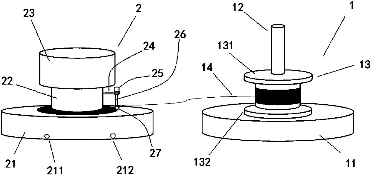
[0015] Such as figure 1 As shown, an optical fiber coiling device set includes an optical fiber transmission device 1 and an optical fiber coiling device 2 .

[0016] The optical fiber transmission device 1 includes a first base 11 and a first rotating shaft 12 vertically arranged at the center of the first base 11. The first rotating shaft 12 is sleeved with an optical fiber reel 13 for rough winding of optical fibers. The optical fiber reel 13 includes an upper optical fiber reel 131 and the lower optical fiber tray 132 , the lower optical fiber tray 132 is in contact with the upper end surface of the base 11 , and the optical fiber 14 is wound between the upper and lower optical fiber trays 131 and 132 .

[0017...


PUM


Abstract

The invention relates to an optical fiber coiling device group comprising an optical fiber transmission device and an optical fiber coiling device. The optical fiber transmission device includes a first base and a first rotating shaft vertically arranged at the center of the first base, wherein the first rotating shaft is provided with an optical fiber disk for coarsely coiling the optical fiber.The optical fiber coiling device includes a second base having a spiral groove for placing an optical fiber on an upper end surface thereof; a second rotating shaft vertically arranged on the center of the second base, and a transmission device disposed on the upper end of the second rotating shaft and in driving connection to the second rotating shaft, wherein a circulating water chamber for cooling the optical fiber is arranged inside the second base, and the sidewall of the second rotating shaft is connected to a coiling member that coils the optical fiber inside the spiral groove. The optical fiber coiling device group integrates optical fiber coiling and water cooling, achieves high-efficiency and high-quality optical fiber coiling and subsequent water-cooling heat dissipation by a mechanical automatic method, and greatly reduces labor cost.

Description

technical field [0001] The invention relates to the technical field of optical fiber performance testing, in particular to an optical fiber coiling device set. Background technique [0002] Aiming at the problems of low efficiency, high cost, easy damage and large error existing in the existing manual optical fiber coiling method, a high-efficiency, high-quality, simple and accurate mechanical coiling method is proposed. [0003] Aiming at the problems of large volume, uneven heat dissipation and blind spots in the existing water-cooled cylinder heat dissipation method, a planar coil method with small size, uniform heat dissipation and omni-directional monitoring is proposed. Contents of the invention [0004] The object of the present invention is to overcome the shortcomings of the prior art and provide a high-efficiency optical fiber coiling device set. [0005] The technical solution of the present invention to solve the above-mentioned technical problems is as follow...

Claims


Application Information

Patent Timeline
Patent Type & Authority Applications(China)
IPC IPC(8): G02B6/44
CPCG02B6/4457
Inventor 李进延刘茵紫廖雷张芳芳贺兴龙陈益沙
Owner EZHOU INST OF IND TECH HUAZHONG UNIV OF SCI & TECH
Why Eureka
Try Eureka