
Reluctance rotor having an additional inherent magnetization

A technology of rotors and rotor slices, applied in the direction of magnetic circuit rotating parts, manufacturing stator/rotor body, magnetic circuit shape/style/structure, etc., can solve problems such as efficiency loss

Active Publication Date: 2018-03-27
SIEMENS AG
View PDF8 Cites 4 Cited by
  • Summary
  • Abstract
  • Description
  • Claims
  • Application Information

AI Technical Summary

Problems solved by technology

This results in a loss of efficiency

Method used


Image

  • Reluctance rotor having an additional inherent magnetization
  • Reluctance rotor having an additional inherent magnetization
  • Reluctance rotor having an additional inherent magnetization

Examples


Embodiment Construction

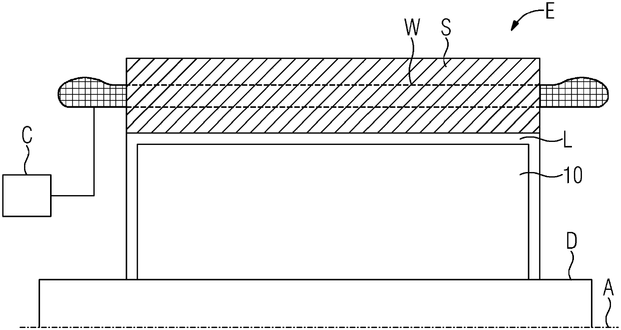
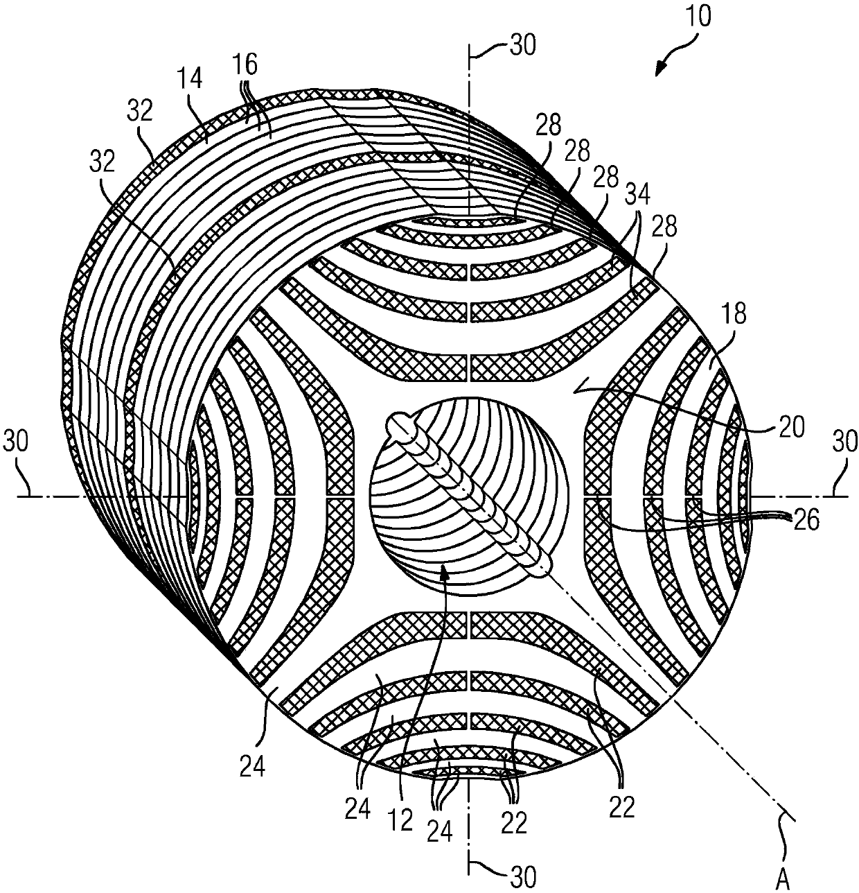
[0037] Through the through hole 12 of the rotor 10 ( figure 2 not shown in ) into shaft D. The diameter of the rotor 10 relative to the axis of rotation A in the radial direction may be greater than 20 cm. The length of the rotor 10 in the axial direction may be greater than 30 cm.

[0038] The rotor 10 has a laminated core 14 formed from a plurality of layers 16 as a magnetically active part. For clarity, in figure 2 Only some of the magnetic layers 16 are provided with reference numerals in . Between these layers there are electrically insulating layers in a known manner in order to prevent eddy currents in the laminated core 14 . exist figure 2 In the example shown, each layer 16 is formed from a soft magnetic rotor sheet 18 . Another name for rotor lamination is electrical steel lamination or transformer lamination.

[0039] exist figure 2 Among them, only the rotor plates 18 located on the end face 20 of the front end of the lamination stack 14 in the axial di...


PUM


Abstract

The invention relates to a rotor (10) for a reluctance machine (E), wherein the rotor (10) has a laminate stack (14) with layers (16), each of the layers having a plurality of flux-conducting portions(24) which are formed in each case by a magnetically conductive rotor lamination (18) and extend between two adjacent d-axes and transversely to a respective q-axis (30), wherein the flux-conductingportions (24) are separated from each other by in each case a flux barrier (22) which is filled with a casting compound. The aim of the invention is to additionally provide a permanent magnetic excitation in the rotor (10) without degrading the reluctance of the rotor. To this end, the invention provides that the casting compound comprises permanently magnetic particles (36) in one or more or eachof the flux barriers (22).

Description

technical field [0001] The invention relates to a rotor for a reluctance electric machine, an electric machine with such a rotor and a method for producing said rotor. The rotor has a laminated core with a plurality of rotor laminations which are electrically insulated from one another. Each rotor lamination may have a strip-shaped flux guiding section for guiding the magnetic flux between the d-axis of the rotor. The flux guiding sections extend along their longitudinal extent obliquely or transversely to the respective q-axis of the rotor and are separated from one another by flux blocking. Background technique [0002] Such a rotor for a reluctance motor is known from US 5 818 140A. Therein, a rotor is described, the laminated core of which consists of rotor laminations which have punched outs. Such rotors are also referred to herein as Vagati rotors. Between the individual flux-conducting sections, air is located in the flux lock produced by the embossing, which acts...

Claims


Application Information

Patent Timeline
Patent Type & Authority Applications(China)
IPC IPC(8): H02K1/24H02K1/27H02K15/03H02K15/12
Inventor 克劳斯·比特纳马尔科·赛尔尼罗伯特·格赖纳曼弗雷德·奥克森屈恩马蒂亚斯·瓦尔穆特
Owner SIEMENS AG
Learn More