
Self-adhesion device of impermeable membrane joint and self-adhesion type water interception curtain construction method thereof

An anti-seepage film and self-adhesive technology, which is applied in construction, infrastructure engineering, magnetic objects, etc., can solve the problems of poor anti-seepage effect, poor adhesion of the anti-seepage film, and loose lap joints. The effect of water interception and impermeability, tight bonding and smooth lap joint

Active Publication Date: 2021-01-29
XIAN RES INST OF CHINA COAL TECH& ENG GROUP CORP
View PDF7 Cites 4 Cited by
  • Summary
  • Abstract
  • Description
  • Claims
  • Application Information

AI Technical Summary

Problems solved by technology

[0005] The purpose of the present invention is to provide a self-adhesive device for joints of anti-seepage membranes and a method for constructing self-adhesive water-cutting curtains, which can effectively solve the problem of poor bonding of adjacent anti-seepage membranes, loose overlap, and poor anti-seepage effect. Improve the tightness and anti-seepage performance of the lap joints of the anti-seepage membrane while solving the problem of limited vertical laying depth

Method used


Image

  • Self-adhesion device of impermeable membrane joint and self-adhesion type water interception curtain construction method thereof
  • Self-adhesion device of impermeable membrane joint and self-adhesion type water interception curtain construction method thereof
  • Self-adhesion device of impermeable membrane joint and self-adhesion type water interception curtain construction method thereof

Examples


Embodiment 1

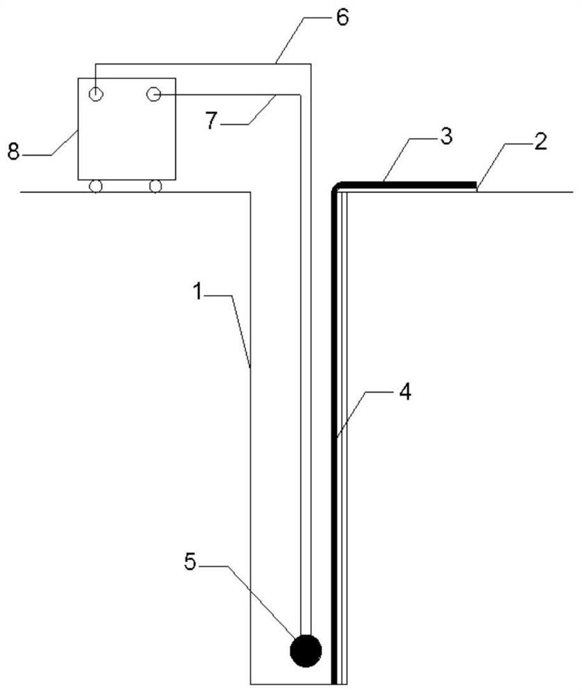
[0051] Step 1: The curtain wall groove section 1 is formed by double-wheel milling or hydraulic grabbing, with a width of 600mm and a depth of 50m. It is generally located in the water-retaining layer and encloses the foundation pit, pollutant diffusion area, open pit or underground mine. .

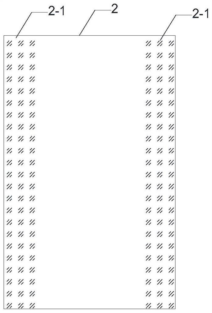
[0052] Step 2: After the curtain wall groove section 1 is formed, lower and lay the first anti-seepage membrane 2 close to the side of the curtain wall groove section 1, and the depth reaches the design depth. The top of the first anti-seepage membrane 2 can be fixed on the curtain wall with rivets. slot 1 slot;

[0053] Step 3: Lay down and lay the second anti-seepage membrane 3 close to the side of the groove section 1 of the curtain wall, and the depth reaches the design depth. The top of the membrane 3 is fixed to the notch of the curtain wall groove section 1 by rivets;

[0054] Step 4: Place the anti-seepage membrane joint self-bonding device on the overlapping section 4 of the fi...

Embodiment 2

[0068] Step 1: The curtain wall groove section 1 is formed by double-wheel milling or hydraulic grabbing, with a width of 600mm and a depth of 50m. It is generally located in the water-retaining layer and encloses the foundation pit, pollutant diffusion area, open pit or underground mine. .

[0069] Step 2: After the curtain wall groove section 1 is formed, lower and lay the first anti-seepage membrane 2 close to one side of the curtain wall groove section 1, the depth reaches the design depth, and the top of the first anti-seepage membrane 2 is fixed to the curtain wall groove with rivets Segment 1 notch;

[0070] Step 3: Lay down and lay the second anti-seepage membrane 3 close to the side of the groove section 1 of the curtain wall, and the depth reaches the design depth. The top of the membrane 3 is fixed to the notch of the curtain wall groove section 1 by rivets;

[0071] Step 4: Repeat steps 2 to 3 to bond all the first anti-seepage membranes 2 and the connected secon...

Embodiment 3

[0075] Step 1: The curtain wall groove section 1 is formed by double-wheel milling or hydraulic grabbing, with a width of 600mm and a depth of 50m. It is generally located in the water-retaining layer and encloses the foundation pit, pollutant diffusion area, open pit or underground mine. .

[0076] Step 2: After the curtain wall groove section 1 is formed, lower and lay the first anti-seepage membrane 2 close to one side of the curtain wall groove section 1, the depth reaches the design depth, and the top of the first anti-seepage membrane 2 is fixed to the curtain wall groove with rivets Segment 1 notch;

[0077] Step 3: Lay down and lay the second anti-seepage membrane 3 close to the side of the groove section 1 of the curtain wall, and the depth reaches the design depth. The top of the membrane 3 is fixed to the notch of the curtain wall groove section 1 by rivets;

[0078] Step 4: Place the anti-seepage membrane joint self-bonding device on the overlapping section 4 of ...


PUM

PropertyMeasurementUnit
osmotic coefficientaaaaaaaaaa

Abstract

The invention relates to a self-adhesion device of an impermeable membrane joint and a self-adhesion type water interception curtain construction method thereof. The self-adhesion device comprises animpermeable membrane, a magnetizing rod or magnetizing plate, an anode cable, a cathode cable, a magnetizing and demagnetizing machine and the like, wherein the magnetizing and demagnetizing machine is connected with the magnetizing rod through the cathode cable and the anode cable, the magnetizing and demagnetizing machine enables a coil to generate a transient ultrastrong magnetic field throughinstantaneous pulse large current in the coil, magnetic materials in the coil can be permanently magnetized by the magnetic field, and the magnetizing rod or magnetizing plate is placed in the position of a to-be-activated impermeable membrane joint, so that the impermeable membrane joint is magnetized, the position of the impermeable membrane joint is activated as a cathode joint and an anode joint, and self adhesion of the impermeable membrane joint is realized. Thus, the problems that adjacent impermeable membranes are not firmly bonded, the lap joint is not tight and the impermeable effectis poor can be effectively solved, and the tightness and the impermeable performance of the lap joint of the impermeable membranes are improved while the problem that the vertical laying depth is limited is solved.

Description

technical field [0001] The invention relates to the technical fields of underground anti-seepage and pollution control such as water-cutting curtains for open-pit coal mines, metal mines water-stopping curtains, anti-seepage curtains for underground mines, pollutant isolation, municipal and industrial and civil construction water-cutting curtains, etc., in particular to an anti-seepage curtain A membrane joint self-adhesive device and a self-adhesive water-cutting curtain construction method thereof. Background technique [0002] Most of the open-pit coal mines in my country are located in the sand and pebble layer areas with strong water richness and strong recharge. The stratum has a large permeability coefficient and is recharged by surface rivers. Long-term dredging will cause a large area of ​​groundwater level drop, difficulties in living and production water for surrounding residents, the death of shallow vegetation, land desertification, mine water discharge to pollu...

Claims


Application Information

Patent Timeline
Patent Type & Authority Applications(China)
IPC IPC(8): E02D19/12H01F13/00
CPCE02D19/12H01F13/00H01F13/006
Inventor 王海王晓东王皓石磊许刚刚赵春虎乔伟佟美玲
Owner XIAN RES INST OF CHINA COAL TECH& ENG GROUP CORP
Learn More